


Robertson AP45 Autopilot
Installation
Simrad Robertson AS
Egersund - Norway
Page 5-31
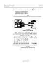
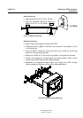
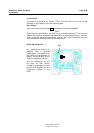
The RI9 is designed for bulkhead or panel mounting, and should be placed in a
location in clear view of the helmsman.
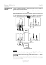
Two or more indicators may be connected in series with the rudder feedback unit.
Note!
If more than one rudder angle indicator is connected, remove the Jumper Switch
S1-S2 on J45S PCB.
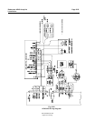
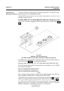
For electrical connection of rudder feedback unit and indicator a 3-wire cable (3 x
1,5 mm
2
- AWG14) should be run. See Fig. 5-37. for connection to junction unit.
Fig. 5-37
RI9 Wiring diagram
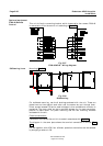
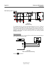
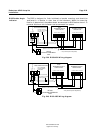
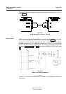
Calibration
The RI9 indicator is calibrated for voltage input signal (RF14XU Rudder Feedback
Unit) and has to be reconnected for current signal from RF45X.
This is done by opening the RI9 and move “jumper” ST3 from “U” to “I” position.
See Fig. 5-38.
Note!
The “Norm”/“Inv” jumper does not affect the meter deflection for current input
signal. If the meter deflection has to be reversed, it must be made in the feedback
unit as described for RF45X.
RI9 Rudder Angle
Indicator