


Page 5-26 Robertson AP45 Autopilot
Installation
Simrad Robertson AS
Egersund - Norway
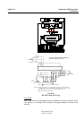
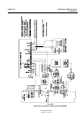
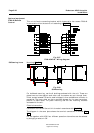
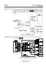
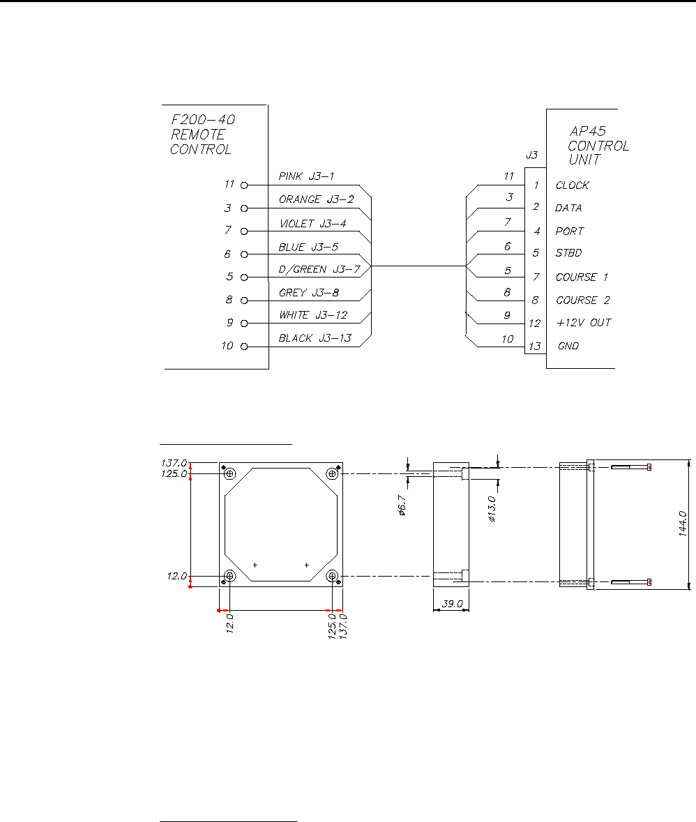
This unit is fixed to a mounting bracket, which is secured by four screws. F200-40
is connected to J3 on the control unit according to Fig. 5-27.
Fig. 5-27
F200-40/AP45 - Wiring diagram
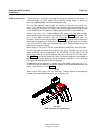
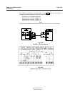
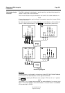
Mounting (Fig. 5-28)
Fig. 5-28
S9 Mounting
For bulkhead mounting, use the 8 bushings enclosed with the unit. These are
placed two and two against each other and the screws are put through them.
Direct contact between S9 and a steel bulkhead is then avoided and corrosion is
prevented. The cover plate can be turned 360 degrees for the most convenient
position of cable outlet. For panel mounting use the two mounting brackets
enclosed with the unit.
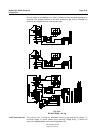
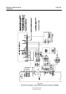
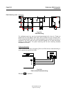
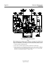
Electrical connection:
Connection to the AP45 Control Unit is made in accordance with Fig. 5-29.
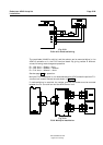
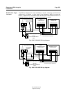
The diagram in the cover plate shows the terminal connections in the S9 (Fig.
5-30).
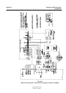
For use together with AP45, four different operation alternatives can be selected
by changing a resistor in S9.
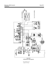
Optional equipment
F200-40 Remote
Control
S9 Steering Lever