


Page II Robertson AP45 Autopilot
Table of contents
Simrad Robertson AS
Egersund - Norway
RI9 Rudder Angle Indicator ........................................................................................4-12
5. INSTALLATION .....................................................................5-1
Unpacking and handling................................................................................................5-1
General ..........................................................................................................................5-1
AP45 Control Unit.........................................................................................................5-1
Connector assemble.......................................................................................................5-2
Heading sensors.............................................................................................................5-4
General ..........................................................................................................................5-4
Magnetic compass .........................................................................................................5-4
RFC35NS Fluxgate Compass........................................................................................5-6
Mounting .......................................................................................................................5-6
Connection.....................................................................................................................5-7
Calibration.....................................................................................................................5-7
Alignment......................................................................................................................5-8
FI100-40 Fluxgate Interface..........................................................................................5-8
G40A Gyro Interface Unit.............................................................................................5-9
G45 Gyro Interface Unit..............................................................................................5-11
RGC Signal Interface Unit...........................................................................................5-12
RF45X Rudder Feedback Unit....................................................................................5-13
RF14XU Rudder Feedback Unit .................................................................................5-14
J45S Junction Unit.......................................................................................................5-19
J45A Junction Unit......................................................................................................5-21
Optional equipment.....................................................................................................5-26
F200-40 Remote Control.............................................................................................5-26
S9 Steering Lever ........................................................................................................5-26
FU91 Steering Lever ...................................................................................................5-28
F1/2 Remote Control...................................................................................................5-30
S35 Steering Lever ......................................................................................................5-30
RI9 Rudder Angle Indicator ........................................................................................5-31
RI35 Rudder Angle Indicator ......................................................................................5-33
Panel mounting............................................................................................................5-34
Bracket mounting ........................................................................................................5-34
Illumination .................................................................................................................5-35
Zero adjust...................................................................................................................5-35
Reversed deflection.....................................................................................................5-35
Connection to Navigation Receiver.............................................................................5-36
Watch alarm ................................................................................................................5-37
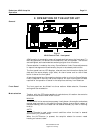
6. START-UP PROCEDURE/ COMMISSIONING.................6-1
Power ON......................................................................................................................6-1
Rudder Feedback Adjustment........................................................................................6-1
Direction of Rudder Movement.....................................................................................6-1
Rudder speed.................................................................................................................6-2
Course Detector Alignment...........................................................................................6-2
Selection of parameter settings......................................................................................6-2
Select language..............................................................................................................6-3
Type of Heading Sensor................................................................................................6-4
Off Course limit.............................................................................................................6-4
Vessel's length...............................................................................................................6-4
Counter rudder...............................................................................................................6-5
Rudder limit...................................................................................................................6-5
Rudder deadband...........................................................................................................6-5
NMEA-format ...............................................................................................................6-5
Disengage of autotrim-function in WORK-mode..........................................................6-5
Disengage of Off Course alarm in Work mode .............................................................6-6
Sea Trial ........................................................................................................................6-6