


Page 5-20 Robertson AP45 Autopilot
Installation
Simrad Robertson AS
Egersund - Norway
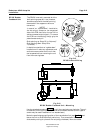
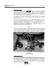
The unit has separate mains supply for the autopilot electronics and the power
unit (motor/solenoids). This reduces the interference to the autopilot electronics
caused by the motor switching. The power unit supply cable (mains supply) should
be of at least 4 mm
2
(AWG10). The electronic supply cable should be 1,5 mm
2
(AWG14).
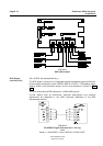
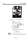
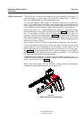
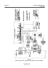
Cables from control unit, rudder feedback unit, power unit and mains supply
should be connected to the terminal blocks according to wiring diagram fig. 5.23.
Sufficient free cable should be left inside the junction unit so that the P.C. board
can be removed for repair without having to disconnect the cables from the
terminal board.
Note!
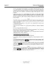
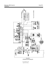
The J45S Junction Unit has been set for 24V DC operation and prewired from
factory to drive Robertson power units with solenoid valves such as RPU3 (solenoid
supply is via J45S).
If the autopilot shall operate on 12 or 32V DC, set voltage selector (plug-in strap)
to appropriate position.
Check that the FB selector is in correct position (S2-S3) for frequency feedback
signal.
Run two voltage feed cables as follows:
Mains input for pump motor and solenoid valves is connected to + and - terminals
marked "Supply" (Cable dimensions 4.0 mm
2
- AWG10).
Autopilot (electronic) supply is connected to + and - terminals marked "Electronic"
(Cable dimensions 1.5 mm
2
- AWG14).
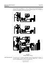
OTHER SOLENOID CONFIGURATIONS
(Driving steering gear solenoids not Robertson supplied).
If the "Supply" cable shall feed solenoid voltage only it may be reduced to 1.5mm
2
-
AWG14.
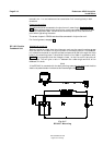
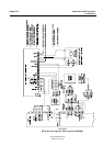
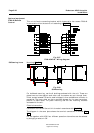
In installations where the unit shall operate solenoids with positive common, they
must be connected according to Fig. 5-24. Note that minus on solenoid supply shall
be connected to "+ Supply"-terminal on J45S.
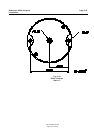
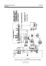
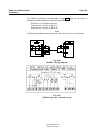
If the unit shall operate solenoids with negative common, they must be connected
according to Fig. 5-25. Note that terminal B must be connected to terminals 15
and 16 by external strapping. Also note that straps S5-S6 and S8-S9 on the PC-
board must be cut.
Note!
(Does not apply for US-installations and only for older version of J200S-40). If the
unit has a PC-board marked "Rev -" and shall operate solenoids with positive
common (Fig. 5-24), there shall be no strap between terminals B and C. Instead
terminal B shall be connected to both terminal 13 and 14.