


Page 5-18 Robertson AP45 Autopilot
Installation
Simrad Robertson AS
Egersund - Norway
VIOLET
BROWN
PINK
BLACK
RED
WHITE
WHITE
BLACK
RED
BLUE (GND)
YELLOW (+5V)
GREEN (WIPER)
NOTE 1
NOTE 2
9810
7
6
5
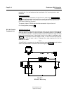
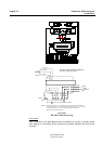
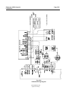
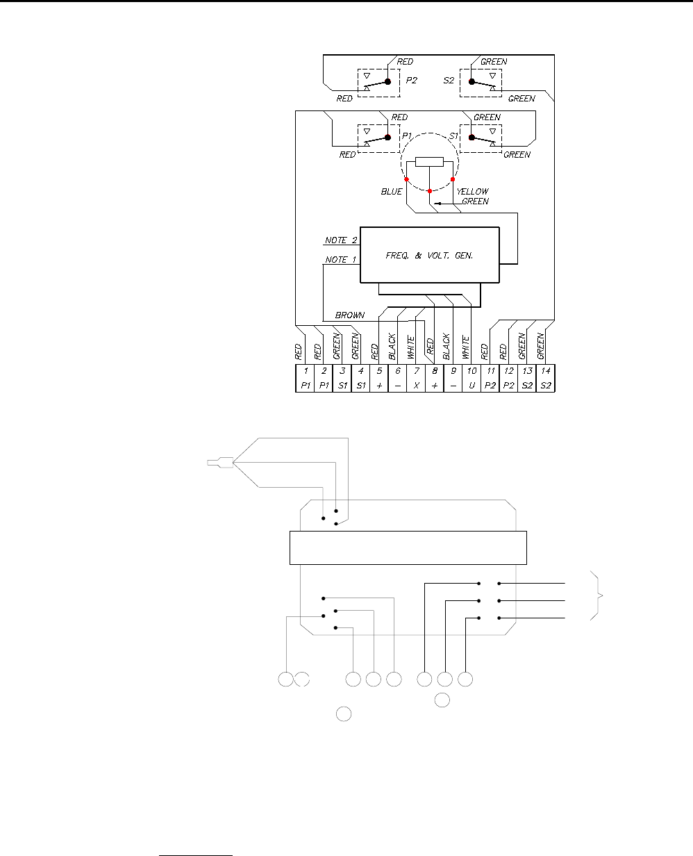
RF14XU ELECTRONIC MODULE
(VIEWED FROM BACK SIDE)
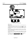
NOTE 1: Brown lead normally connected to .
Move to to invert the rudder indicator deflection.
NOTE 2: Normally connected for +/-45˚ rudder angle (violet, brown and pink leads are
not connected). For +/-60˚ connect brown lead to terminal 10, for +/-70˚ connect
pink lead to terminal 10, for +/-90˚ connect violet lead to terminal 10.
White lead must remain connected.
BROWN
8
9
8
9
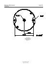
TO
POT.
METER
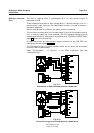
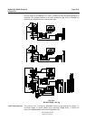
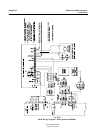
Fig. 5-20
RF14XU Internal wiring
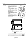
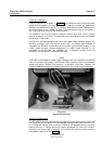
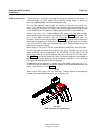
Final check
After installation, the cable glands must be sealed with silicon to prevent water
from seeping in. Also apply silicon grease to the gasket between the bottom and
top cover.