


Robertson AP45 Autopilot
Installation
Simrad Robertson AS
Egersund - Norway
Page 5-29
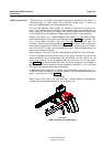
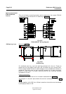
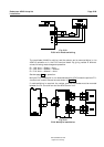
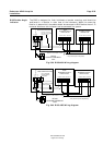
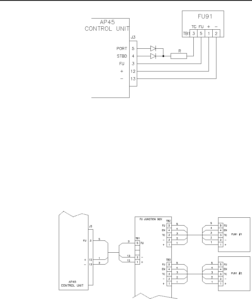
Fig. 5-33
FU91 with mode switching
The two diodes (1N4002 or similar) and the resistor can be mounted either in the
AP45 J3 connector or in the FU91 terminal board. By giving resistor R different
values, following mode changes are possible:
R = 1.0K: Auto → Dodge → Auto
R = 3.0K: Auto → Manual → Manual
R = 5.1K: Auto → Manual → Auto
See also page 2-14 for operation.
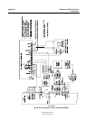
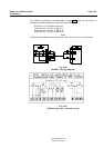
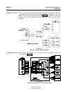
Multiple FU91 installation is not recommended with AP45 unless the optional FU-
Junction box is used. Connections are shown in Fig. 5-34
If mode switching is required, the resistor and the two diodes must be mounted
between the FU-Junction box and the AP45 Control unit.
Fig. 5-34
FU91 Multiple installation