


Robertson AP45 Autopilot
Installation
Simrad Robertson AS
Egersund - Norway
Page 5-17
Electrical installation
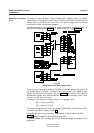
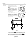
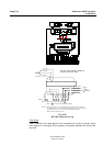
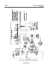
Electrical connection is shown in Fig. 5-21. The cables are carried through cable
glands and connected to the terminal board. If required, to avoid any mechanical
damage, the cables should be run in a conduit between the rudder feedback unit
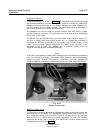
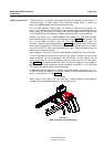
and the junction unit or rudder indicator. The cable screen must be connected to
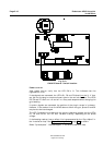
the internal ground terminal. Ref. picture below.
The feedback unit has an external ground terminal and must have a proper
ground connection to the hull. The grounding wire should be as short as possible
and at least 10 mm wide.
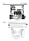
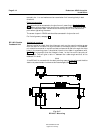
The RF14XU can be powered either from the rudder angle indicator supply (19-
40V DC) or directly from the autopilot junction unit. If a rudder angle indicator is
connected, the RF14XU is powered from the rudder angle indicator supply. If the
rudder angle indicator voltage disappears, or rudder angle indicator is not
connected to the RF14XU, the feedback unit is powered directly from the
autopilot. The change over is done automatically.
Note!
If RF14XU is connected to rudder angle indicators, and the indicators are powered
from an unfiltered 24V supply, the enclosed 470uF capacitor should be connected
across the supply. Without the capacitor, a deviation may occur between the
autopilot feedback midposition reference and that of the rudder angle indicator(s).
Fig. 5-19
Screen termination
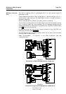
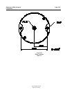
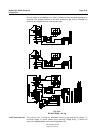
Scaling of rudder angle
The RF14XU is normally delivered for ±45 degrees rudder angle (violet, brown and
pink leads are not connected). For ±60 degrees, connect brown lead to terminal 10,
for ±70 degrees, connect pink to terminal 10 and for ±90 degrees, connect the violet
lead to terminal 10. White lead must remain connected. To invert the indicator
deflection, the brown lead to terminal 8 of the RF14XU terminal board must be
connected to terminal 9. See Fig. 5-20.