


Page 5-30 Robertson AP45 Autopilot
Installation
Simrad Robertson AS
Egersund - Norway
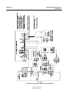
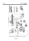
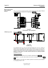
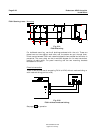
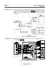
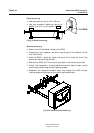
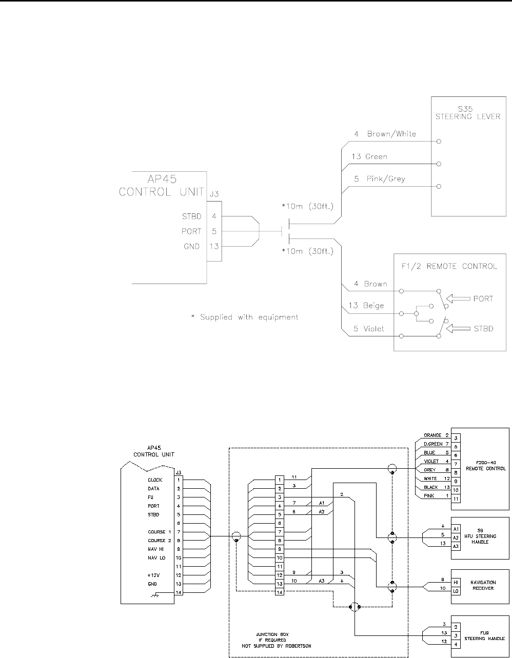
The unit is mounted to bulkhead or panel by two screws from the front. The cable
is connected to the junction unit according to Fig. 5-35. Interchange the port and
stbd wires to the screw terminals in the junction unit if necessary to make the
direction of the lever movement coincide with the direction of the rudder
movement.
Fig. 5-35
S35, F1/2 - AP45 - Wiring diagram
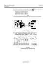
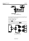
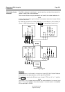
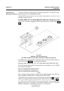
This handheld remote control with 10 m (30 ft.) cable is connected to the control
unit as shown in Fig. 5-35.
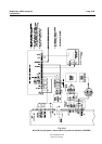
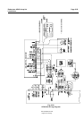
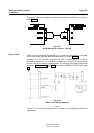
Fig. 5-36
AP45 Wiring diagram - J3 w/multiple input
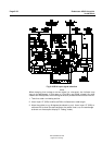
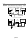
F1/2 Remote Control
S35 Steering Lever