


Robertson AP45 Autopilot
Installation
Simrad Robertson AS
Egersund - Norway
Page 5-37
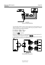
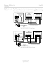
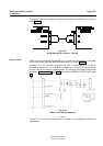
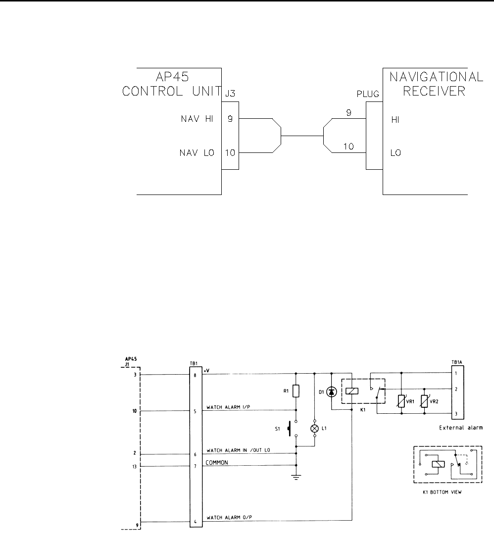
The output from the navigational receiver is connected to AP45 J3 pin 9 and 10
(Ref. Fig. 5-44).
Fig. 5-44
AP45/Navigation receiver - Wiring
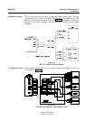
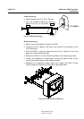
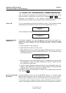
AP45 is originally designed for connection to an external watch alarm of type WA9
which is no longer available. WA9 was connected to J1 as per Fig. 5-45
However, it is still possible to enable the built in watch alarm in AP45 by
temporarily connect pin 2 of J1 (Watch al. sense) to pin 13 (Gnd). The watch alarm
function can be permanently disabled again by following the procedure described
in section “Fault warnings” page 2-16 and section “TROUBLE SHOOTING”, page
7-1
Fig. 5-45
WA9 Circuit/Wiring diagram
Note!
If pin 2 of J1 has a fixed connection to pin 13 (Gnd) it is not possible to disable the
watch alarm.
Watch alarm