


Robertson AP45 Autopilot
Installation
Simrad Robertson AS
Egersund - Norway
Page 5-33
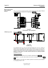
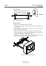
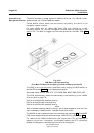
The RI35 is designed for flush, bulkhead or bracket mounting, and should be
positioned in a location in clear view of the helmsman. When the mounting
location is determined, the cables should be connected to RI35 before the unit is
mounted. Maximum two indicators can be connected in a system.
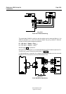
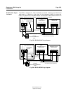
* Non polarized (colour independant)
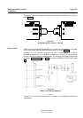
J45A JUNCTION UNIT
RF45X
RUDDER FEEDBACK
UNIT
121110
GND
RUDDER FB I/P
+OUT
BLUE
GREEN
RED
*
FREQ SUPPLYCURR
RI35
RUDDER ANGLE
INDICATOR
SUPPLY VOLTAGE 12-24V
RI35
RUDDER ANGLE
INDICATOR
FREQ SUPPLY
CURR
12
*
Do not connect
this wire in a dual
RI35 system
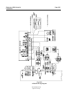
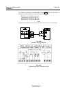
Fig. 5-39 RI35-J45A Wiring diagram
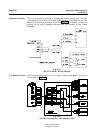
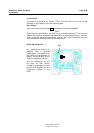
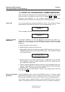
* Non polarized (colour independant)
J45S JUNCTION UNIT
RF45X
RUDDER FEEDBACK
UNIT
121110
GND
RUDDER FB I/P
+OUT
BLUE
GREEN
RED
*
FREQ SUPPLYCURR
RI35
RUDDER ANGLE
INDICATOR
SUPPLY VOLTAGE 12-24V
RI35
RUDDER ANGLE
INDICATOR
FREQ SUPPLY
CURR
*
Do not connect
this wire in a dual
RI35 system
Use a separate
terminal for this
connection
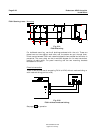
Fig. 5-40 RI35-J45S Wiring diagram
RI35 Rudder Angle
Indicator