


Page 5-14 Robertson AP45 Autopilot
Installation
Simrad Robertson AS
Egersund - Norway
manually h.o. - h.o. and make sure the transmission link is moving freely in both
directions.
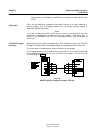
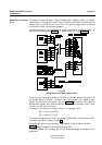
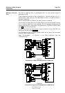
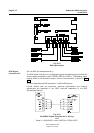
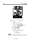
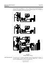
Electrical connection
The cable should be connected to the junction unit according to Fig. 5-23 - Fig.
5-26. When splicing cable in the junction box, use the enclosed crimp pins on each
wire of the extension cable. Otherwise the wires may be cut off at the terminal
point when tightening the screw.
The screen is open in RF45X and should be connected in the junction unit.
For final alignment, see page 6-1.
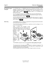
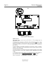
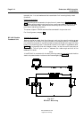
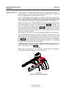
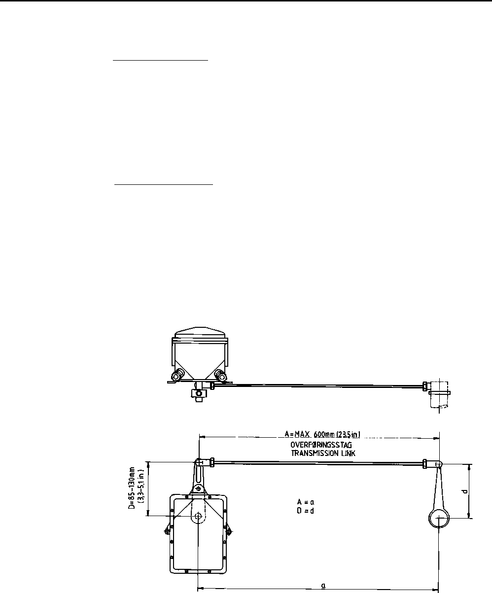
Mechanical mounting
Before installation check that the alignment mark on the mounting plate agrees
with the mark on the shaft. Bring the rudder to Amidships position. The feedback
unit should be mounted on a plane surface and secured by bolts through the three
holes in the mounting plate. It should be linked to the rudder in accordance with
Fig. 5-17. It is important that the linkage is linear, i.e. the A-a and D-d are pairs of
equal length. This will give a ratio 1:1 between the rudder angle and that of the
feedback unit shaft.
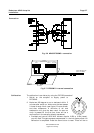
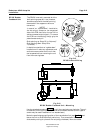
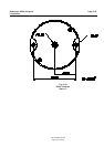
Note!
If the RF14XU is mounted with the shaft pointing upwards, the yellow and the blue
lead to the potentiometer inside must be interchanged (See Fig. 5-20).
Fig. 5-17
RF14XU - Mounting
RF14XU Rudder
Feedback Unit