


APIcom Instruction Manual Configuration
Tab Property Description
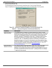
General
(continued)
Save network
configuration
automatically on
exit
If checked, APIcom will automatically save the network
configuration when it exits. If it’s not checked and the
configuration is modified, APIcom will prompt to save the
configuration when it exits. This is useful to temporarily modify
some settings but not save them.
Confirm deleting
items when
editing
configuration
If checked, APIcom will prompt for all delete actions.
Use checkboxes
in configuration
trees
If checked, APIcom will attempt to use checkboxes in
configuration trees. Some versions of Windows do not support
the checkboxes.
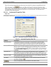
Front Panel Update all front
panel displays at
this periodic
interval (seconds)
If checked, APIcom will update all the front panel windows at the
specified periodic rate. The default is checked and set to 10
seconds. When using slow connections, this setting should not
be set too low. For example, if 5 instruments are simultaneously
connected over a 2400 baud connection, and the update period
is set to 5 seconds, APIcom will not be able to fetch the display
contents from all 5 instruments within 5 seconds. This will result
in display requests getting queued up, which will make APIcom
appear unresponsive to key presses. In this example, an update
interval of 15 seconds is more appropriate. Keep in mind that the
front panel display is always refreshed immediately whenever a
button is pressed. If this option is unchecked, APIcom will only
refresh the front panel when a button is pressed.
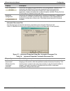
Logging
(Advanced
Feature)
Log commands
sent to
instruments
If checked, APIcom will write each command that it sends to an
instrument to the log file.
Log responses
received from
instruments
If checked, APIcom will write each response that it receives from
an instrument to the log file.
Log errors If checked, APIcom will write error messages to the log file.
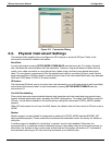
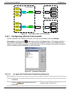
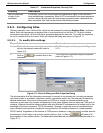
2.5. The APIcom Network: Instruments and Sites.
Cable, Modem and Ethernet Connections
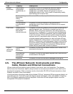
APIcom works with three distinct types of objects: instruments, sites, and connectors. The diagram
below shows how these three objects (using modems as connectors) are related to each other and to
the physical equipment. Other connectors can be: direct cable, RS-232 to Ethernet converter or direct
Ethernet connection (future instruments)
In the figure below, everything inside the box labeled “APIcom” represents APIcom program objects, not
physical equipment. From left to right, the diagram shows instruments, sites, and modems. Everything
else in the diagram represents physical equipment. Notice how APIcom program objects mirror the
arrangement of the physical equipment.
05499 Rev. A 2-5