


LIST OF FIGURES
Number Title Page
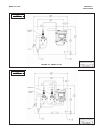
2-1 Model FCL-01 .................................................................................................... 7
2-2 Model FCL-02 .................................................................................................... 7
3-1 Analog Output Connections .................................................................................... 9
3-2 Alarm Relay Connections......................................................................................... 10
3-3 Wiring Diagram for Free Chlorine Sensor ................................................................ 11
3-4 Wiring Diagram for 399VP-09 pH Sensor ............................................................... 11
3-5 Wiring Diagram for 3900VP-10 pH Sensor (gray cable) ......................................... 11
3-6 Wiring Diagram for 3900VP-10 pH Sensor (blue cable) .......................................... 11
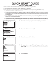
4-1 Main Display............................................................................................................. 13
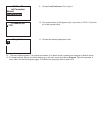
4-2 Programming Screen Showing Item List.................................................................. 13
4-3 Arrow Bar ................................................................................................................. 13
4-4 Analyzer Keypad ...................................................................................................... 14
4-5 Navigation Keys ....................................................................................................... 14
5-1 High Alarm Logic ..................................................................................................... 26
5-2 Low Alarm Logic ...................................................................................................... 26
5-3 Operation of the Interval Timer................................................................................. 26
6-1 Sensor Current as a Function of Free Chlorine Concentration ................................ 39
6-2 Calibration Slope and Offset .................................................................................... 42
8-1 Chlorine Sensor Parts .............................................................................................. 55
8-2 Replacement Parts for the Flow Controller Assembly used in Model FCL-01.......... 57
8-3 Replacement Parts for the Flow Controller Assembly used in Model FCL-02.......... 58
9-1 Pin Out Diagram for Model 499ACL-01-VP Sensor ................................................ 61
9-2 Pin Out Diagram for Model 3900VP Sensor............................................................. 61
9-3 Simulating Chlorine .................................................................................................. 70
9-4 Simulating pH Inputs ................................................................................................ 71
9-5 Three-Wire RTD Configuration................................................................................. 72
9-6 Simulating RTD Inputs.............................................................................................. 72
MODEL FCL-1056 TABLE OF CONTENTS
LIST OF TABLES CONT’D
9.6.1 Calibration Error During Two-Point Calibration ........................................................ 67
9.7 Troubleshooting When No Error Message is Showing - General............................. 70
9.9.2 Simulating pH Input.................................................................................................. 71
9.10 Simulating Inputs Temperature................................................................................. 72
iii