


6
MODEL FCL-1056 SECTION 2.0
INSTALLATION
2.2 INSTALLATION
2.2.1 General Information
1. Although the system is suitable for outdoor use, do not install it in direct sunlight or in areas of extreme
temperature.
2. To keep the analyzer enclosure watertight, install plugs (provided) in the unused cable openings.
3. Install the system in an area where vibrations and electromagnetic and radio frequency interference are
minimized or absent.
4. Be sure there is easy access to the analyzer and sensors.
2.2.2 Sample Requirements
Be sure the sample meets the following requirements:
1. Temperature: 32 to 122ºF (0 to 50ºC)
2. Pressure: 3 to 65 psig (122 to 549 kPa abs)
3. Minimum flow: 3 gal/hr (11 L/hr)
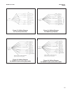
2.2.3 Mounting, Inlet, and Drain Connections
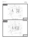
The FCL is intended for wall mounting only. Refer to Figure 2-1 or 2-2 for details. The sensor(s) screw into the flow
cell adapters as shown in the figures. For Model FCL-02 (free chlorine with continuous pH adjustment), the pH
sensor must be installed as shown in Figure 2-2.
A 1/4-inch OD tubing compression fitting is provided for the sample inlet. If desired, the compression fitting can
be removed and replaced with a barbed fitting. The fitting screws into a 1/4-inch FNPT check valve. The check
valve prevents the sensor flow cells from going dry if sample flow is lost.
The sample drains through a 3/4-inch barbed fitting. Attach a piece of soft tubing to the fitting and allow the waste
to drain open atmosphere. Do not restrict the drain line.
Adjust the sample flow until the water level is even with the central overflow tube and excess water is flowing down
the tube.
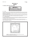
2.2.4 Electrical Connections
Refer to Section 3.1 for details.
2.2.5 Installing the Sensor(s)
The FCL is provided with sensor cables pre-wired to the analyzer. Connect the chlorine sensor (Model 499ACL-
01-54-VP) to the cable labeled CL. Connect the pH sensor (Model 3900VP-02-10 or older Model 399VP-09) to the
cable labeled pH. The terminal end of the sensor is keyed to ensure proper mating with the cable receptacle. Once
the key has slid into the mating slot, tighten the connection by turning the knurled ring clockwise.
The sensor(s) screw into the plastic fitting(s), which are held in the flow cell(s) by the union nut. Do not remove the
protective cap on the sensor(s) until ready to put the sensor(s) in service.
CAUTION
The FCL free chlorine system is NOT suitable for use
in hazardous areas.