


9.9 SIMULATING INPUTS — pH
9.9.1 General
This section describes how to simulate a pH input into
the analyzer. To simulate a pH measurement, connect a
standard millivolt source to the analyzer. If the analyzer
is working properly, it will accurately measure the input
voltage and convert it to pH.
9.9.2 Simulating pH input.
1. Set automatic temperature correction to manual
and set manual temperature to 25°C. Turn off solu-
tion temperature correction. See Section 5.6
2. Disconnect the sensor and connect a jumper wire
between the IN REFERENCE and IN pH terminals.
3. Press DIAG and choose sensor 2 (pH). The input
voltage should be 0 mV and the pH should be 7.00.
Because calibration data stored in the analyzer may
be offsetting the input voltage, the displayed pH may
not be exactly 7.00.
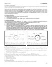
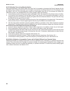
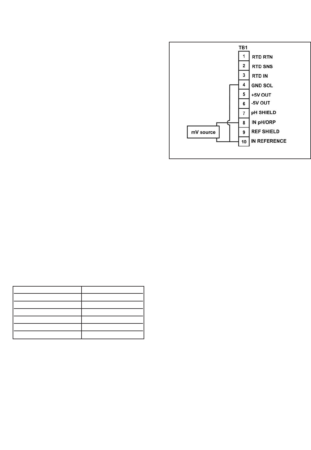
4. If a standard millivolt source is available, discon-
nect the jumper wire between IN REFERENCE and
IN pH and connect the voltage source as shown in
Figure 9-4. Be sure to jumper the IN REFERENCE
and GND SOL terminals.
5. Calibrate the analyzer using the procedure in
Section 6.4.4. Use 0.0 mV for Buffer 1 (pH 7.00)
and -177.4 mV for Buffer 2 (pH 10.00). If the ana-
lyzer is working properly it should accept the cali-
bration. The slope should be 59.16 mV/pH and the
offset should be zero.
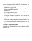
6. To check linearity, return to the main display and the
pH/temperature/mV screen. Set the voltage source
to the values shown in the table and verify that the
pH and millivolt readings match the values in the
table.
71
MODEL FCL-1056 SECTION 9.0
TROUBLESHOOTING
Voltage (mV) pH (at 25°)
295.8 2.00
177.5 4.00
59.2 6.00
-59.2 8.00
-177.5 10.00
-295.8 12.00
FIGURE 9-4. Simulating pH Input.