


MODEL FCL-1056 SECTION 9.0
TROUBLESHOOTING
9.3.4 Sensor Incompatible
This error message means that the sensor board software is not supported by the main board software. Either the
sensor board or the main board software is too old.
Replace the main board with one compatible with the sensor board. Call the factory for assistance. You will be
asked for the main and sensor board software revision numbers. To read the main board software revision, press
the DIAG key and scroll down until Instr SW Ver is showing. To view the sensor board software revision, press
the DIAG key, choose the appropriate sensor, and scroll down until Board SW Ver is showing. The main board
can be replaced only at the factory.
9.3.5 Sensor CPU Error
This message means the sensor board software is corrupted.
1. Cycle the power off then on.
2. If cycling the power does not help, call the factory. The sensor board must be replaced.
9.3.6 Sensor RTD Open
The chlorine and pH sensors used in the FCL contain a Pt 100 RTD (resistance temperature device) for
measuring temperature. Sensor RTD open means the temperature measuring circuit is open.
1. Confirm that the sensor RTD wires are properly connected.
2. Confirm that the Varipol connector is properly seated.
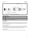
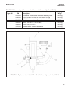
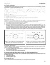
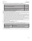
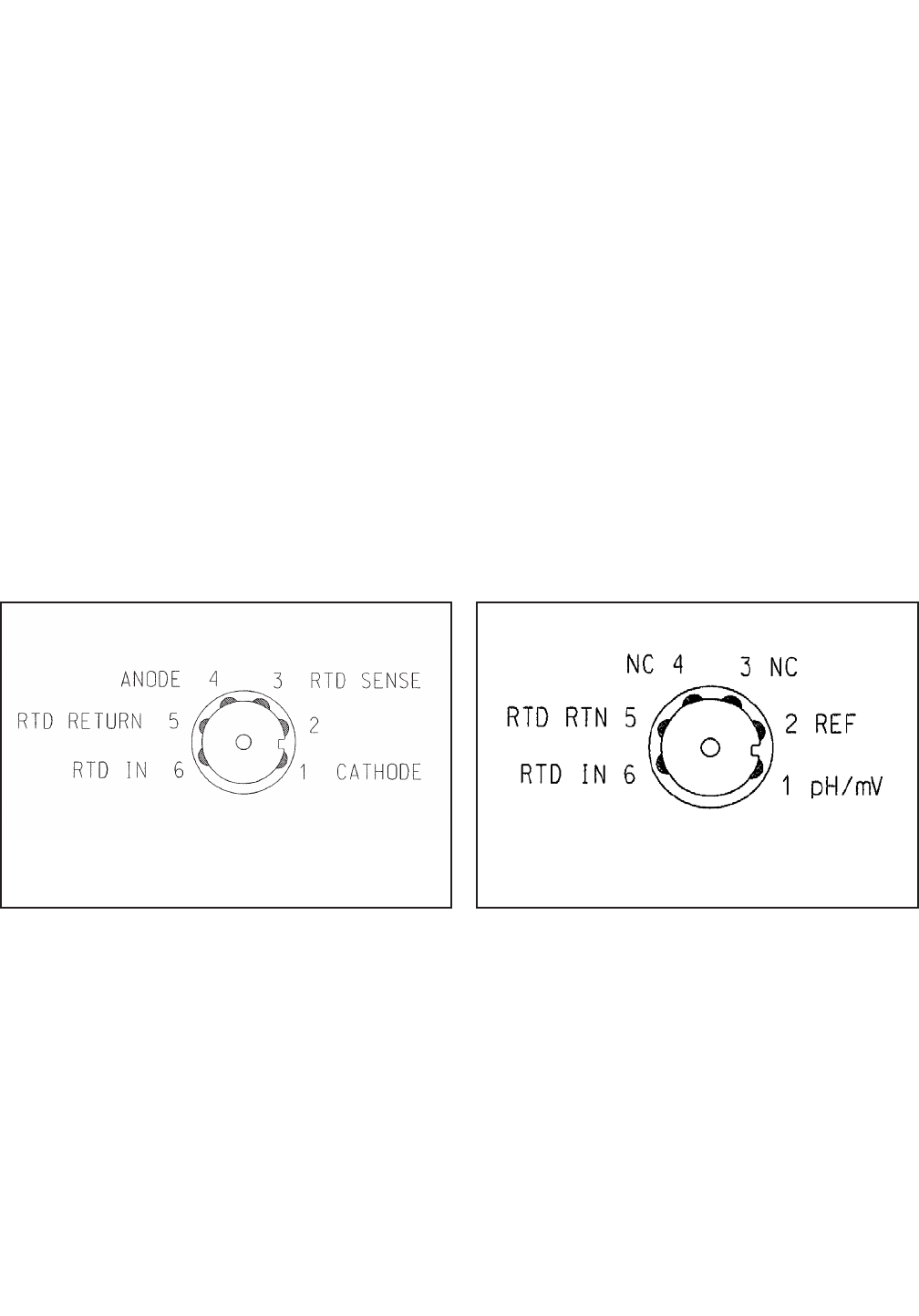
3. Disconnect the sensor from the cable and use an ohmmeter to check the resistance across the RTD. See
Figures 9-1 and 9-2. At room temperature it should be about 110Ω. If the resistance is very high, the RTD
has failed and the sensor must be replaced. If the resistance is okay, connect the Variopol cable to the
sensor and disconnect the three RTD wires at the analyzer. Measure the resistance across the red and white
RTD leads. If the resistance is very high, the problem is with the VP cable, and it must be replaced.
FIGURE 9-1. Pin Out Diagram for Model 499ACL-01-VP
Sensor (top view of connector end of sensor)
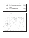
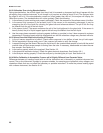
FIGURE 9-2. Pin Out Diagram for Model 3900VP
Sensor (top view of connector end of sensor)
9.3.7 Sensor 1 Not Detected
The ribbon cable from sensor 1 (chlorine) board must be plugged into the sensor 1 plug. See Figure 3-1 for the
location of the sensor board connectors.
1. Confirm that the ribbon cable connecting sensor 1 (chlorine) board to the main board is plugged into the Sensor 1
connector on the main board.
2. Confirm that the ribbon cable is seated at both ends.
9.3.8 Sensor Factory Data, Sensor Board User Data, and Sensor EEPROM Write Error
These messages mean factory eeprom data or user eeprom data on the sensor board is corrupted or the CPU on
the sensor board is bad.
1. Cycle power off then on.
2. Replace the sensor board.
9.3.9 Sensor ADC Error
There is a bad component on the sensor board. The sensor board must be replaced.
61