


5.4.2 Definitions
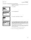
1. ASSIGNING ALARMS. There are four alarms
relays. The relays are freely assignable to any sen-
sor and to either the measurement (for example,
chlorine) or temperature. Alarm relays can also be
assigned to operate as interval timers or as fault
alarms. A fault alarm activates when the analyzer
detects a fault in either itself or the sensor.
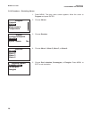
2. FAULT ALARM. A fault condition exits when the
analyzer detects a problem with a sensor or with
the analyzer itself that is likely to cause seriously
erroneous readings. If an alarm was programmed
as a fault alarm, the alarm will activate. At the same
time a fault message will appear in the main dis-
play.
3. ALARM LOGIC, SETPOINTS, AND DEADBANDS.
See Figures 5-1 and 5-2.
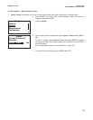
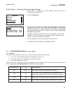
4. INTERVAL TIMER. Any alarm relay can be used as
an interval timer. Figure 5-3 shows how the timer
operates. While the interval timer is operating, the
main display, analog output, and assigned alarms
for the sensor(s) can be put on hold. During hold,
the main display remains at the last value.
5. SYNCHRONIZE TIMER. If two or more relays are
being used as interval timers, choosing synchro-
nize timers will cause each timer to start one
minute later than the preceding timer.
26
MODEL FCL-1056 SECTION 5.0
PROGRAMMING THE ANALYZER
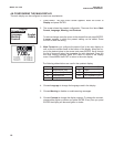
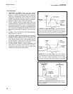
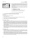
FIGURE 5-2. Low alarm logic. The alarm activates
when the chlorine concentration drops below the low set-
point. The alarm remains activated until the reading
increases above the value determined by the dead-band.
FIGURE 5-3. Operation of the interval timer. The num-
bers in parentheses are the allowed values for each
timer parameter.
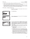
FIGURE 5-1. High alarm logic. The alarm activates
when the chlorine concentration exceeds the high set-
point. The alarm remains activated until the reading
drops below the value determined by the deadband.