


MODEL FCL-1056 SECTION 3.0
WIRING
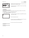
3.2 SENSOR WIRING
The Model FCL is provided with sensor cables pre-wired to the analyzer. If it is necessary to replace the sensor
cable, refer to the instructions below.
1. Shut off power to the analyzer.
2. Loosen the four screws holding the front panel in place and let it drop down.
3. Locate the appropriate signal board.
4. Loosen the gland fitting and carefully push the sensor cable up through the fitting as you pull the board
forward to gain access to the wires and terminal screws. Disconnect the wires and remove the cable.
5. Insert the new cable through the gland and pull the cable through the cable slot.
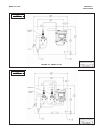
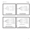
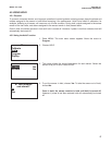
6. Wire the sensor to the signal board. Refer to the wiring diagrams in Figures 3-3 and 3-4.
7. Once the cable has been connected to the board, slide the board fully into the enclosure while taking up the
excess cable through the cable gland. Tighten the gland nut to secure the cable and ensure a sealed enclosure.
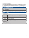
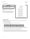
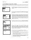
Slot 1 (left) Slot 2 (center) Slot 3 (right)
communication input 1 (chlorine) input 2 (pH)
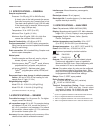
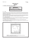
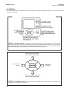
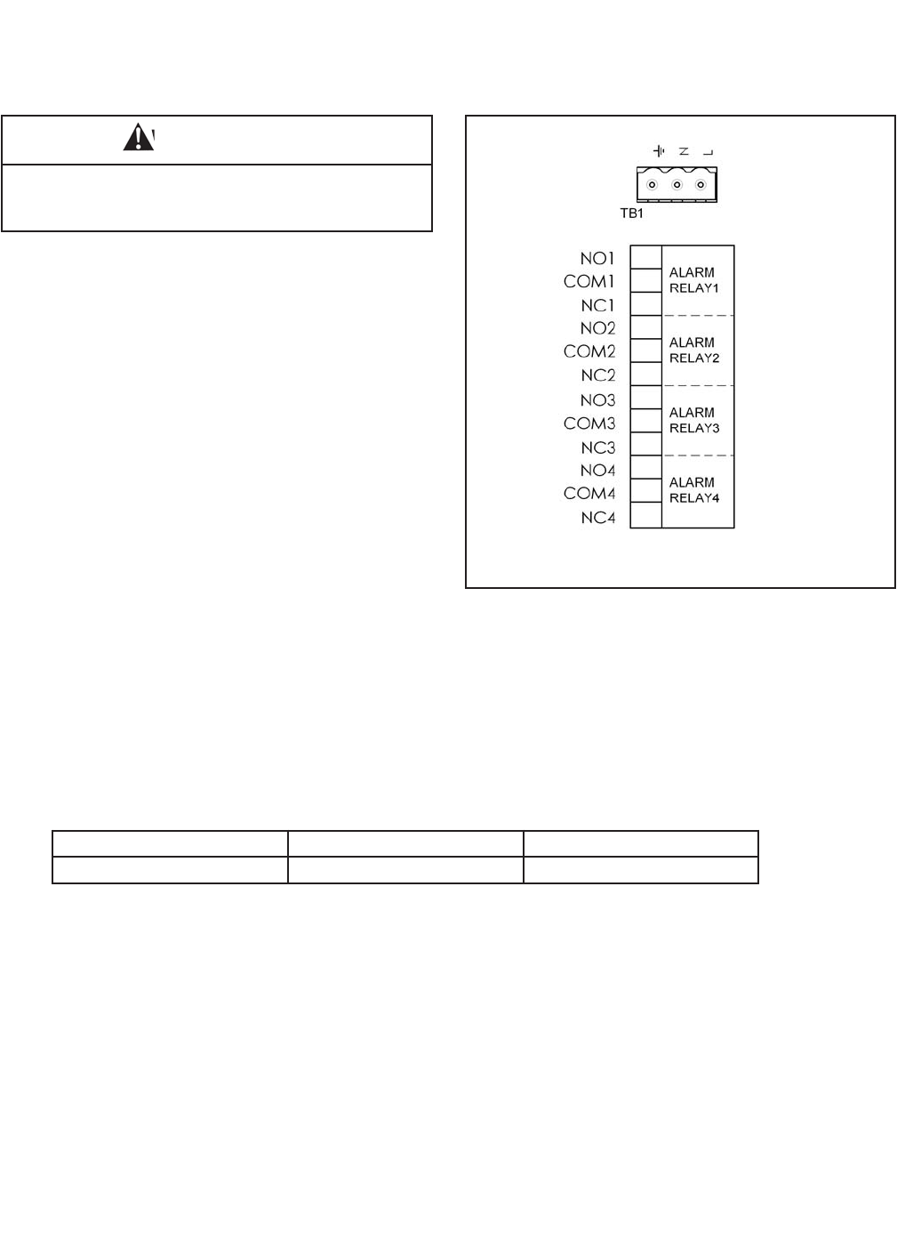
3.1.3 Alarm wiring.
The alarm relay terminal strip is located just below the
power connector on the power supply board. See
Figure 3-2.
Keep alarm relay wiring separate from signal wiring.
Do not run signal and power or relay wiring in the
same conduit or close together in a cable tray.
FIGURE 3-2. Alarm relay connections.
10
WARNING
Exposure to some chemicals may degrade the sealing
properties used in the following devices: Zettler
Relays (K1-K4) PN AZ8-1CH12DSEA