


56
MODEL FCL-1056 SECTION 8.0
MAINTENANCE
8.4 CONSTANT HEAD FLOW CONTROLLER
8.4.1 General
After a period of time, deposits may accumulate in the constant head overflow chamber and in the tubing leading
to the flow cell(s). Deposits increase the resistance to flow and cause the flow to gradually decrease. Loss of flow
may ultimately have an impact on the chlorine sensor performance. The flow controller is designed to provide about
2 gal/hr (120 mL/mm) flow. Loss of flow to about 1 gal/hr (60 mL/mm) causes about a 5% decrease in chlorine
sensor output. Loss of flow has almost no effect on pH sensor performance other than to increase the overall
response time.
8.4.2 Cleaning the flow controller
The low flow controller can be taken apart completely for cleaning. Use a strong flow of water to flush out the tub-
ing. A pipe cleaner or a small bottlebrush can remove more adherent deposits. To prevent leaks, apply a thin layer
of silicone grease (or equivalent) to the two O-rings at the base of overflow chamber and to the O-ring sealing the
central overflow tube to the base.
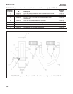
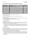
8.4.3 Other Maintenance
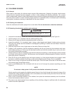
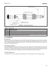
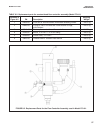
Table 8-2 and Figure 8-2 show the replacement parts for the flow controller assembly used in Model FCL-01. Table
8-3 and Figure 8-3 show replacement parts for the flow controller assembly used in Model FCL-02.