


SECTION 3.0.
WIRING
MODEL FCL-1056 SECTION 3.0
WIRING
3.1 POWER, ALARM, AND OUTPUT WIRING
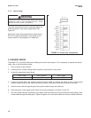
3.1.1 Power
Wire AC mains power to the power supply board, which is mounted vertically on the left hand side of the analyz-
er enclosure. The power connector is at the top of the board. Unplug the connector from the board and wire the
power cable to it. Lead connections are marked on the connector. (L is live or hot; N is neutral, the ground con-
nection has the standard symbol.)
AC power wiring should be 14 gauge or greater. Run the power wiring through the conduit opening nearest the
power terminal. Provide a switch or breaker to disconnect the analyzer from the main power supply. Install the
switch or breaker near the analyzer and label it as the disconnecting device for the analyzer.
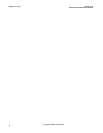
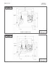
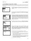
3.1.2 Analog output wiring
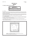
Two analog current outputs are located on the main circuit board, which is attached to the inside of the enclosure
door. Figure 3-1 shows the location of the terminals. The connectors can be detached for wiring. TB-1 is output 1.
TB-2 is output 2. Polarity is marked on the circuit board.
For best EMI/RFI protection, use shielded output signal cable enclosed in earth-grounded metal conduit.
Keep output signal wiring separate from power wiring. Do not run signal and power or relay wiring in the same
conduit or close together in a cable tray.
FIGURE 3-1. Analog output connections. The analog outputs are on the main
board near the hinged end of the enclosure door.
9
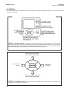
Electrical installation must be in accordance with
the National Electrical Code (ANSI/NFPA-70)
and/or any other applicable national or local codes.
WARNING
RISK OF ELECTRICAL SHOCK