177
Selection of operation mode and operation location
4
PARAMETERS
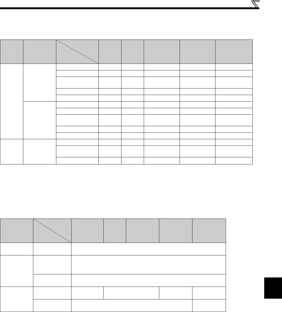
(2) Controllability through communication
Controllability through communcation in each operation mode is shown below.
Monitoring and parameter read can be performed from any operation regardless of operation mode.
∗1 As set in Pr.338 Communication operation command source and Pr. 339 Communication speed command source (Refer to page 176)
∗2 At occurrence of RS-485 communication error, the inverter cannot be reset from the computer.
∗3 Enabled only when stopped by the PU. At a PU stop, PS is displayed on the operation panel. As set in Pr. 75 PU stop selection. (Refer to page 158)
∗4 Some parameters may be write-disabled according to the Pr. 77 Parameter write selection setting and operating status. (Refer to page 161)
∗5 Some parameters are write-enabled independently of the operation mode and command source presence/absence. When Pr. 77 = "2", write is enabled.
(Refer to the parameter list on page 56) Parameter clear is disabled.
∗6 Available with multi-speed setting and terminal 4-5 (valid when AU signal is ON).
(3) Operation at error occurrence
∗1 Can be selected using Pr. 75 Reset selection/disconnected PU detection/PU stop selection.
∗2 Can be selected using Pr. 122 PU communication check time interval.
∗3 In the PU JOG operation mode, operation is always stopped when the PU is disconnected. Whether fault (E.PUE) occurrence is allowed or not is as set in
Pr. 75 Reset selection/disconnected PU detection/PU stop selection.
Operation
Location
Condition
(Pr. 551 Setting)
Operation
Mode
Item
PU
Operation
External
Operation
External/PU
Combined
Operation Mode 1
(
Pr. 79
= 3)
External/PU
Combined
Operation Mode 2
(Pr. 79 = 4)
NET Operation
Control by
RS-485
communica
tion from
PU
connector
2
(PU connector)
Run command (start)
××
×
Run command (stop)
∆ ∗3 ∆ ∗3
×
Running frequency
setting
×
××
Parameter write
∗4
× ∗5
∗4 ∗4
× ∗5
Inverter reset
×
Other than the
above
Run command (start) ×× × ×
∗1
Run command (stop) ×× × ×
∗1
Running frequency
setting
×× × ×
∗1
Parameter write × ∗5 × ∗5 × ∗5 × ∗5
∗4
Inverter reset ×× × ×
∗2
Control
circuit
external
terminals
—
Inverter reset
Run command
(start, stop)
×
×× ∗1
Frequency setting ×
∆ ∗6
× ∗1
: Enabled, ×: Disabled, ∆: Some are enabled
Error Definition
Operation
Mode
Condition
(
Pr. 551
setting)
PU Operation
External
Operation
External/PU
Combined
Operation Mode
1
(Pr. 79 = 3)
External/PU
Combined
Operation Mode
2
(Pr. 79 = 4)
NET Operation
Inverter
fault
—Stop
PU
disconnection of
the PU
2 (PU connector)
9999 (automatic
recognition)
Stop/continued ∗1, ∗3
Other than the
above
Stop/continued∗1
RS-485
communication
error of the PU
connector
2 (PU connector)
Stop/
continued∗2
Continued
Stop/
continued∗2
—
Other than the
above
Continued
Stop/
continued∗2


