224
Special operation and frequency control
(5) Parameter details
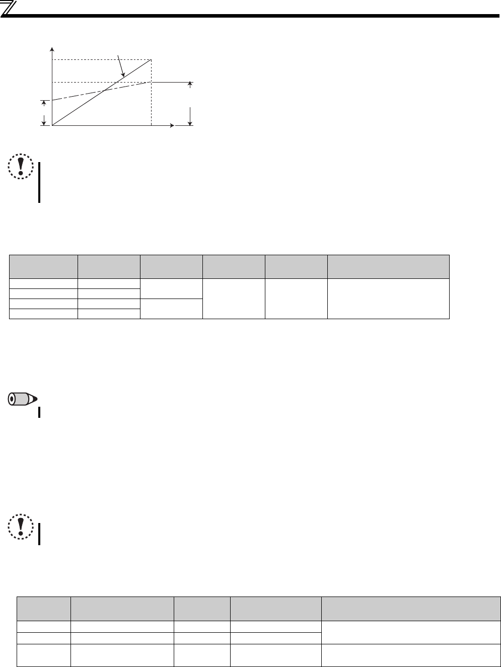
When ratio (Pr. 128 = "42, 43") is selected for addition method, PID
control × (ratio of main speed) is added to the main speed. The ratio is
determined by the Pr. 125 Terminal 2 frequency setting gain frequency and
C2 (Pr. 902) Terminal 2 frequency setting bias frequency. The frequency
setting signal is set to 0 to 60Hz in the range between 0 to 100% in the
initial setting. The ratio is (×100%) when the main speed is 60Hz and
(×50%) when 30Hz.
Turning X14 signal on/off during operation by assigning X14 signal results in the following operation.
When X14 signal is on: Uses output frequency unchanged as the main speed command and continues operation by
dancer control.
When X14 signal is off: Ends dancer control and continues operation at the set frequency made valid.
Action of Pr. 129 PID proportional band, Pr. 130 PID integral time, Pr. 131 PID upper limit, Pr. 132 PID lower limit, Pr. 134 PID
differential time is the same as PID control. For the relationship of controlled variable (%) of PID control and frequency, 0%
is equivalent to the set frequency of Pr. 902 and 100% to Pr. 903 .
For the Pr. 133 PID action set point setting, set frequency of Pr. 902 is equivalent to 0% and Pr. 903 to 100%. When 9999 is
set in Pr. 133, 50% is the set point.
(6) Output signal
Output terminal assignment during dancer control (PID control) operation
PID signal turns on during dancer control (PID control) or at a stop by PID control (in the status PID operation being
performed inside) (The signal is OFF during normal operation.)
For the terminal used for PID signal output, assign the function by setting "47 (positive logic) or 147 (negative logic)" in Pr.
190 or Pr. 192 (output terminal function selection).
(7) PID monitor function
The PID control set point and measured value can be output to the operation panel monitor display and terminal AM.
For each monitor, set the following value in Pr. 52 DU/PU main display data selection and Pr. 158 AM terminal function selection.
(8) Priorities of main speed command
The priorities of the main speed speed command source when the speed command source is external are as follows.
JOG signal > multi-speed setting signal (RL/RM/RH/REX)
> temrinal 2
The priorities of the main speed speed command source when "3" is set in Pr. 79.
Multi-speed setting signal (RL/RM/RH/REX) > set frequency (digital setting by PU, operation panel)
Terminal 4 can not be selected as the main speed speed command even when AU terminal is turned ON.
Even when a remote operation function is selected by setting a value other than "0" in Pr. 59, compensation of the remote
setting frequency to the main speed is ignored (changes to 0).
NOTE
Even when C4 (Pr. 903) is set to other than 100%, the frequency setting signal is considered as 100%.
Even when C3 (Pr. 903) is set to other than 0%, the frequency setting signal is considered as 0%.
When C2 (Pr .902) is set to other than 0Hz, the frequency setting signal is 0% when C2 (Pr. 902) is less than the set
frequency.
Pr. 128 Setting PID Action
Addition
Method
Set Point
Measured
Value
Main Speed Command
40 Reverse action
Fixed
Pr. 133 Terminal 4
Speed command for each
operation mode
41 Forward action
42 Reverse action
Ratio
43 Forward action
REMARKS
Pr. 127 PID control automatic switchover frequency is invalid.
NOTE
Changing the terminal function using any of Pr. 178 to Pr. 182, Pr. 190, Pr. 192 may affect the other functions. Make
setting after confirming the function of each terminal.
Setting Monitor Description
Minimum
Increments
Terminal AM
Full Scale
Remarks
52 PID set point
0.1% 100%
—
53 PID measured value
0.1% 100%
54 PID deviation
0.1% —
Value cannot be set in Pr. 158.
Displays 1000 when the PID deviation is 0%.
C2(Pr. 902)
Output frequency
0
Frequency setting signal
100%
Initial value
Bias
Pr. 12
5
Gain
60Hz


