


D Logs Summary
MiLLennium GPSCard SW Version 4.503/4.52 Command Descriptions Manual Rev 2 199
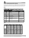
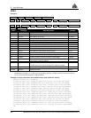
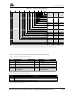
Notes on Table D-5:
1. Bit 3: On OEM GPSCards, “ROM” includes all forms of non-volatile memory.
2. Bits 12-15: Flag is reset to 0 five minutes after the last overrun/overload condition has occurred.
GPSCard example:
All OK = 0000 0000 0000 1010 0000 0000 1111 1111 (binary) = 000A00FF (hexadecimal); using a VCTCXO oscillator.
RECEIVER STATUS - DETAILED BIT DESCRIPTIONS OF SELF-TEST
Bit 0 Antenna
1 This bit will be set to 1 if the antenna connection is not drawing excessive current.
0 If the antenna connections are shorted together then this bit will be clear (0) indicating a possible antenna
port problem.
Bit 1 L1 PLL
1 When the L1 RF downconverter passes self-test, the bit will be set to 1.
0 If a fault is detected in the L1 RF downconverter, this bit is set to 0.
Bit 2 RAM
1 When this bit is set to 1, the receiver RAM has passed the self-test requirements.
0 If the bit has been set to 0, then RAM test has failed; please contact NovAtel Customer Service.
Bit 3 ROM (Note: “ROM” includes all forms of nov-volatile memory (NVM))
1 When this bit is set to 1, the receiver ROM test has passed the self test requirements.
0 A zero bit indicates the receiver has failed the ROM test.
Bit 4 DSP
1 This bit will be set to 1 when the digital signal processors (DSP) have passed the self-test requirements.
0 0 indicates one or both of the DSP chips has failed self-test; please contact NovAtel Customer Service.
Bit 5 L1 AGC
1 When set to 1, the L1AGC circuits are operating within normal range of control.
0 This bit will be set clear if the L1 AGC is operating out of normal range. Intermittent setting of the AGC
bit indicates that the card is experiencing some electro-magnetic interference of a very short duration.
Continuous setting of the AGC bit may indicate that the card is receiving too much signal power from the
antenna or that a more serious problem with the card may exist. Failure of this test could be the result of
various possibilities, such as: bad antenna LNA, excessive loss in the antenna cable, faulty RF
downconverter, or a pulsating or high power jamming signal causing interference. If this bit is
continuously set clear, and you cannot identify an external cause for the failed test, please contact
NovAtel Customer Service.
Bit 6 COM1
1 When set to 1, the COM1 UART has passed the self-test requirements.
0 If set to 0, the COM1 UART has failed self-test and cannot be used for reliable communications.
Bit 7 COM2
1 When set to 1, the COM2 UART has passed the self-test requirements.
0 If set to 0, the COM2 UART has failed self-test and cannot be used for reliable communications.
Bits 8, 9, 10 Week / No Coarsetime / No Finetime
0 These bits indicate the state of the receiver time and are set only once, generally in the first few minutes
of operation, in the presence of adequate numbers of satellite signals to compute position and time.
1 If these bits are not all set to zero, then the observation data, pseudorange measurement, carrier-phase, and
Doppler measurements may jump
as the clock adjusts itself.
Bit 11 L1 Jammer Detection
0 Normal operation is indicated when this bit is 0.