


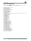
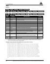
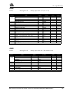
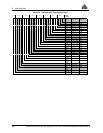
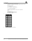

D Logs Summary
200 MiLLennium GPSCard SW Version 4.503/4.52 Command Descriptions Manual Rev 2
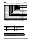
1 If set to 1, the receiver has detected a high power signal causing interference. When this happens, the
receiver goes into a special anti-jamming mode where it re-maps the A/D decode values as well as special
L1AGC feedback control. These adjustments help to minimize the loss that will occur in the presence of
a jamming signal. You should monitor this bit, and if set to 1, do your best to remedy the cause of the
jamming signal. Nearby transmitters or other electronic equipment could be the cause of interference;
you may find it necessary to relocate your antenna position if the problem persists.
Bits 12, 13, 14 Buffer COM 1 / COM 2
0 Normal operation is indicated by a 0 value.
1 These bits are set to 1 to inform the user when any of the 8-Kilobyte output buffers have reached an over-
run condition (COM1 or COM2). Over-run is caused by requesting more log data than can be taken off
the GPSCard because of bit rate limitations or slow communications equipment. If this happens, the new
data attempting to be loaded into the buffer will be discarded. The receiver will not load a partial data
record into an output buffer. The flag resets to 0 five minutes after the last overrun occurred.
Bit 15 CPU Overload
0 Normal operation is indicated by a 0 value.
1 A value of 1 indicates that the CPU is being over-taxed. This may be caused by requesting an excessive
amount of information from the GPSCard. If this condition is occurring, limit redundant data logging or
change to using binary data output formats, or both. You should attempt to tune the logging requirements
to keep the idle time above 20% for best operation. If the average idle % drops below 10% for prolonged
periods of time (2-5 seconds), critical errors may result in internal data loss and the over-load bit will be
set to 1. You can monitor the CPU % idle time by using the RvSA log message. The flag resets to 0 five
minutes after the first overload occurred.
NOTE: As the amount of CPU power becomes limited, the software will begin to slow down the position
calculation rate. If the CPU becomes further limited, the software will begin to skip range measurement
processing. Priority processing goes to the tracking loops.
Bit 16 Almanac Saved
0 Almanac not saved in non-volatile memory.
1 Almanac saved in non-volatile memory (12 channel OEM cards only).
Bit 17 L2 AGC
1 When set to 1, the L2 AGC circuits are operating within normal range of control.
0 This bit will be set clear if the L2 AGC is operating out of normal range. Intermittent setting of the AGC
bit indicates that the card is experiencing some electro-magnetic interference of a very short duration.
Continuous setting of the AGC bit may indicate that the card is receiving too much signal power from the
antenna or that a more serious problem with the card may exist. Failure of this test could be the result of
various possibilities, such as: bad antenna LNA, excessive loss in the antenna cable, faulty RF
downconverter, or a pulsating or high power jamming signal causing interference. If this bit is
continuously set clear, and you cannot identify an external cause for the failed test, please contact NovAtel
Customer Service.
Bit 18 L2 Jammer Detection
0 Normal operation is indicated when this bit is 0.
1 If set to 1, the receiver has detected a high power signal causing interference. When this happens, the
receiver goes into a special anti-jamming mode where it re-maps the A/D decode values as well as special
L2AGC feedback control. These adjustments help to minimize the loss that will occur in the presence of
a jamming signal. You should monitor this bit, and if set to 1, do your best to remedy the cause of the
jamming signal. Nearby transmitters or other electronic equipment could be the cause of interference; you
may find it necessary to relocate your antenna position if the problem persists.
Bit 19 L2 PLL
1 When the L2 RF downconverter passes self-test, the bit will be set to 1.
0 If a fault is detected in the L2 RF downconverter, this bit is set to 0.