


B Multipath Elimination Technology
78 MiLLennium GPSCard SW Version 4.503/4.52 Command Descriptions Manual Rev 2
The Model 600 GPSAntenna is an active antenna designed to operate at the GPS L1 and L2 frequencies, 1575.42
and 1227.60 MHz. It incorporates NovAtel’s innovative, patent pending Pinwheel Technology - a unique aperture
coupled slot array configuration. The microstrip receiving elements is coupled to a low-noise amplifier (LNA). The
unit is optimized to receive right-hand-circularly-polarized signals, and its radiation pattern is shaped to reduce
signals arriving at low elevation angles; these features decrease the errors associated with electromagnetic
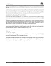
interference and multipath. Also, the model 600 gain pattern roll-off compares well to a patch antenna roll-off
mounted on a large choke ring ground plane. This antenna provides comparable performance to the choke ring
ground plane antenna while being much lighter and smaller.
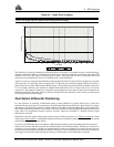
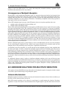
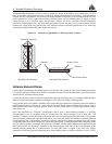
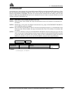
Figure B-3 Illustration of Quadrifilar vs. Microstrip Patch Antennae
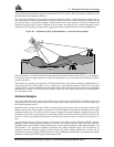
Antenna Ground Planes
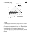
Nearby objects can influence the radiation pattern of an antenna. Thus, one of the roles of the antenna ground plane
is to create a stabilizing artificial environment on which the antenna rests and which becomes a part of the antenna
structure and its resultant radiation pattern.
A small ground plane (relative to one wavelength at the operating frequency) may have minimal stabilizing effect,
whereas a large ground plane (multiple wavelengths in size) will have a highly stabilizing effect.
Large ground planes also exhibit a shielding effect against RF signal reflections originating below the antenna’s
radiation pattern horizon. This can be a very effective low angle shield when the antenna is elevated on a hill or
other structure above other reflecting surfaces such as vehicles, railway tracks, soil with high moisture content,
water bodies, etc.
One of the drawbacks of a "flat plate" ground plane is that it gives a “hard boundary condition”, i.e. allowing
electromagnetic waves to propagate along the ground plane and diffract strongly from its edge. The “soft
boundary” condition, on the other hand, will prevent the wave from propagating along the surface of the ground
plane and thereby reducing the edge diffraction effects. As a result the antenna will exhibit a completely different
radiation pattern. The “soft boundary” condition is typically achieved by a quarter wavelength deep, transversely
corrugated ground plane surface (denoted as “choke ring ground plane”). When the depth of the corrugation (choke
rings) is equal to a quarter wavelength, the surface wave vanishes, and the surface impedance becomes infinite and
hence provides the “soft boundary” condition for the electromagnetic field. This results in modifications to the
antenna radiation pattern that is characterized by low back lobe levels, no ripples in the main lobe, sharper
amplitude, roll-off near the horizon and better phase center stability (there are smaller variations in 2 axes). This is
Quadrifilar Elements
Radome
Antenna Patch
Dielectric
Patch Ground Plane
Quadrifilar Helix Antenna Microstrip Patch Antenna