


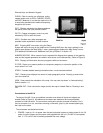
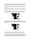
WHAT COMES IN THE BOX
Before installing your new NS 10, please ensure that the following parts are included in the box:
NS 10 Navigational System………………………………………….NS 10 USCHO
GR-1 receiver………………………………………………………..GR-1
4” stainless steel stem mount………………………………………...402237-1
¼” ABS spacer……………………………………………………….N/A
Hole cover……………………………………………………………HC
Escutcheon plate……………………………………………………..N/A
Gimbal mounting bracket……………………………………………M-LCR P
Mounting hardware…………………………………………………..MHX-D3
1” – 14 threaded mounting bolt……………………………………...N/A
40 foot receiver cable………………………………………………..490098-1
4 foot power cable…………………………………………………...490080-2
1 foot NMEA output cable…………………………………………..490095-1
1 foot DGPS input cable……………………………………………..490141-1
120 VAC power adapter (US products only)………………………..401426-3
Instructional video tape……………………………………………...530309-1
Lock nut……………………………………………………………..N/A
Receiver gasket……………………………………………………...N/A
Stern gasket………………………………………………………….N/A
If any one of these items is missing, please see your Humminbird dealer or contact Humminbird
at our Customer Service Hotline, listed on the rear cover.
In addition to the parts supplied with your NS 10, you will also need the following for installation
and operation:
- A drill and several drill bits
- Phillips-head screw driver
- Ruler or measuring tape
- Flat-head screw driver
- Pen or pencil
- 12 volt DC power source (your boat’s battery)
- 1-amp fuse (if you connect the unit directly to the battery)
- Silicone sealant
For best results, please read all the mounting instructions before you begin installation, and
follow them carefully. Improper installation can result in poor reception and affect the accuracy of
the navigational system.
CHOOSING A MOUNTING LOCATION FOR THE RECEIVER
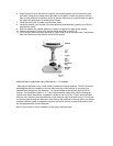
Before mounting the receiver, gather the parts you will need: The receiver, 4” stem mount, ¼”
spacer, gasket, receiver cable, escutcheon plate, and mounting hardware.
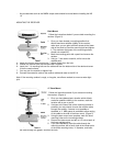
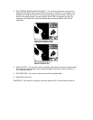
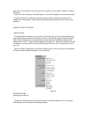
Next, choose the mounting option to use. The receiver can be mounted directly to a flat surface (
Figure 3) with a maximum wall thickness of 3/8”. The lower side must be accessible to insert the
fastener.
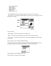
Or the receiver can be mounted on he 4” stern mount provided (Figure 4 & 5). The stern mount
can be mounted directly to a flat horizontal surface, or if no access for cable routing is available,
the ¼” ABS spacer can be installed between the mounting surface to provide a side for the cable.