


- 5 -
1.1.2 Pre-operation procedure
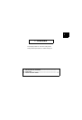
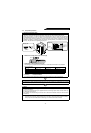
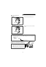
1. Unpacking and product check
Unpack the product and check the capacity plate on the front cover and the rating plate on the equipment
side face to ensure that the type and output rating agree with your order and the product is intact.
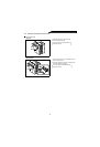
When using reactors 1, 2 and the external box, especially when they are used with the Mitsubishi
transistorized inverter be sure to use them as a set and make sure they are securely connected. This
high power factor converter suppresses harmonics according to the harmonic suppression guidelines
published by Ministry of Economy Trade and Industry (formerly Ministry of International, Trade and
Industry). Pay attention to the applicable capacity, etc.
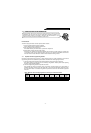
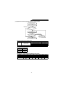
• Definition of the high power factor converter type
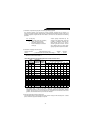
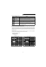
• Confirmation of the peripheral device types
The following three peripheral devices, FR-HCL01, FR-HCL02 and FR-HCB, must be installed.
Confirm their types:
High Power Factor Converter
Reactor 1 Reactor 2 External Box
FR-HC-7.5K FR-HCL01-7.5K FR-HCL02-7.5K FR-HCB-7.5K
FR-HC-15K FR-HCL01-15K FR-HCL02-15K FR-HCB-15K
FR-HC-30K FR-HCL01-30K FR-HCL02-30K FR-HCB-30K
FR-HC-55K FR-HCL01-55K FR-HCL02-55K FR-HCB-55K
Note: 400V class devices have capacity numbers preceded by H in their type codes.
• Accessory . . . . . . Instruction manual
If you have found any discrepancy, damage, etc., please contact your sales representative.
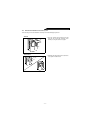
2. Installation
To operate the product with high performance for a long time, install it in a proper place, in a correct
direction, and with proper clearances. (See page 13.)
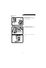
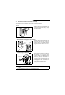
3. Wiring
Securely connect the power supply, reactors 1, 2, external box, high power factor converter and inverter
to the terminal blocks.
If they are connected improperly, the peripheral devices and the high power factor converter itself may
be damaged. (See page 16.)
After making sure that the wiring is secured, refer to the inverter instruction manual on how to set the
parameters.
Note: If the inverter is provided with a jumper connector for sink and source logic change, fit the jumper
connector to the sink logic (factory setting) when connecting a high power factor converter (FR-HC).
If the jumper connector is fitted to the source logic, the converter cannot be connected.
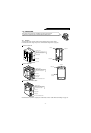
Applicable power
supply
Capacity plate
High power factor
converter type
Serial number
Rating plate
Rated input
current
Serial number
Converter type
Applicable inverter
capacity
FR-HC- K
Symbol
None
H
Voltage class
200V class
400V class
Capacity in "kW"
Symbol
7.5 to 55
Applicable inverter capacity