


- 21 -
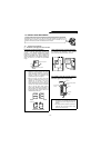
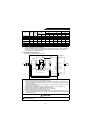
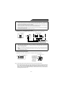
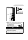
6) Wiring the reactor 1 and high power factor converter
Supply power to the power detecting terminals (R, S, T) independently of the main circuit wiring.
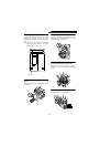
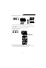
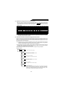
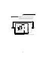
7) Wiring the power supply and inverter
Supply power to the inverter independently of the high power factor converter (FR-HC).
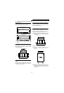
Note: 1.Remove the jumpers across terminals R-R1 and S-S1 of the inverter control circuit.
2.Always connect the power supply to the inverter which has the alternate power supply input terminals
R1, S1. Power for the inverter’s control power and large-capacity cooling fan (200V 15K or more/
400V 11K or more) will be supplied. Otherwise the inverter may come to an alarm stop or be
damaged. Refer to the inverter instruction manual to check whether the inverter has the alternate
power supply input terminals or not.
Note: 1.The high power factor converter (FR-HC) operates as a common converter. Use terminals P, N to
connect it with the inverter. Always keep the inverter’s power input terminals R, S, T open. If they
are connected accidentally, the inverter will be damaged. Opposite polarity of terminals P, N will
damage the inverter and high power factor converter.
2.The size of the cables for connection of terminals P, N should be the same as that used in the
power supply side of the inverter. (Refer to the inverter instruction manual.)
3.Refer to the inverter instruction manual for the inverter terminal to be connected to terminal RDY of
the high power factor converter.
4.Do not insert the NFB between terminals P-N (P-P, N-N).
Note: 1.Terminals R, S, T of the high power factor converter (FR-HC) are control terminals designed to
detect power supply phases. Before wiring, it is necessary to match the phases of terminals R4,
S4, T4 with those of terminals R, S, T. If wiring is incorrect, the high power factor converter (FR-
HC) will not operate properly.
2.The R, S, T terminals of the high power factor converter (FR-HC) must be connected to the power
supply.
Running the inverter without connecting the terminals to the power supply will damage the high
power factor converter (FR-HC).
Reactor 1
Power
supply
High power factor converter
control circuit terminals
R
S
T
R
S
T
Overall wiring distance: Within 10m
Cable size: 1.25mm
2
High power factor converte
r
control circuitReactor 1
R
S
T
R
S
T
NFB
Power
supply
R1
S1
Inverter control power supply
Cable size:0.75 to 2mm
2
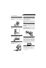
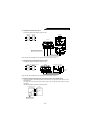
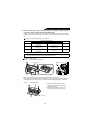
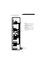
Terminal block for control circui
t
Pull out.
1) Loosen the upper screws.
2) Remove the lower screws.
3) Pull out the jumpers toward
you and remove.
4) Conncet the cables of the
other control circuit power
supply to the lower
terminals (R1, S1).
5) Tighten the upper
screws without fail.