


- 29 -
2.1 PARAMETER UNIT
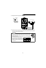
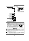
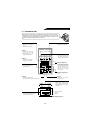
2.1.1 Structure of the parameter unit
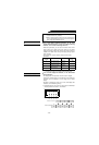
The parameter unit (FR-PU02E
-1
) is installed directly to the high power factor converter or
connected to it by the cable (FR-CBL) to allow parameters to be set and data to be
monitored. Note that as compared to the inverter, there are restrictions on functions. In this
manual, the parameter unit may be referred to as the PU.
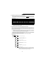
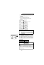
FR-PU02E
-1
PARAMETER UNIT
Overload signal detecting
indication
Display unit
Indicates the driving (FWD) or
re
g
enerative
(
RV
)
mode.
POWER ALARM
FR-PU02E
-1
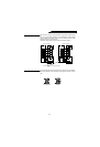
Help key
• Used to call the help selection
screen.
• Note that there are restrictions.
Clear key
• Used to clear a set value entered.
• Used to return to the help
selection screen when you have
selected an invalid help item.
Shift key
• Used to shift to the next item in
the setting or monitoring mode.
Numeral keys
• Used to enter the parameter
number and set value.
Read key
• Used also as a decimal point key.
• Acts as a key to select or read any of various functions.
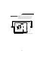
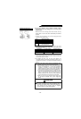
PU main monitor
• Three different monitors can be selected
in sequence with the [SHIFT] key.
Display
• Shows the monitor screen, etc.
Mode selecton keys
• Used to select the setting mode
and monitoring mode. The “EXT
OP” and “PU OP” keys are invalid.
Frequency change keys
• On the monitoring, parameter or
help item selection screen, these
keys are used to move the cursor.
Hold down the SHIFT key and
press either of these keys to
advance or return the display
screen one page.
Operation command keys
• Invalid.
Write key
• Used to write a set value in the
setting mode, etc.
Converter LED display
• POWER (yellow) indicates whether
power is supplied or not and ALARM
(red) indicates whether alarm output is
provided or not.