


- 51 -
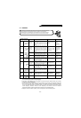
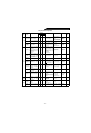
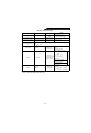
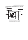
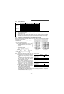
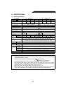
Measuring Points and Instruments
Note 1: Do not use a tester because accurate data will not be obtained.
* Values in parentheses indicate those for 400V class.
Item Measuring Point Measuring Instrument
Remarks
(Reference Measured Value)*
Power supply voltage
V1
Across R-S, S-T and T-R
Moving-iron type AC
voltmeter
Commercial power supply
170 to 242V (342 to 506V) 50Hz
170 to 253V (342 to 506V) 60Hz
Power supply side current
I1
R, S and T line currents
Moving-iron type AC
ammeter
Power supply side power
P1
At R, S and T, and across R-
S, S-T and T-R
Electrodynamic type
single-phase wattmeter
P
1
=W11+W12+W13
(3-wattmeter method)
Power supply side power factor
Pf1
Calculate after measuring power supply voltage, power supply side current and power supply side
power.
Pf
1
= × 100%
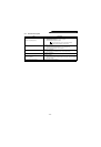
Converter output Across P-N
Moving-coil type
(such as tester)
Inverter LED display is lit.
1.35 × V1
Max. 380V (760V) during
regenerative operation
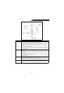
Meter signal Across FM(+)-SD
Moving-coil type
(Tester, etc. may be used)
(Internal resistance:
50kΩ or larger)
Approx. 5VDC at max. frequency
(without meter)
Pulse width T1: Adjusted
with Pr. 900
SD is common.
Approx. 10VDC at maximum
frequency
(without frequency meter)
20 to 30VDC when open.
ON voltage: 1V or less
Alarm signal
Across A-C
Across B-C
Moving-coil type
(such as tester)
Continuity check
<Normal> <Fault>
Across A-C:
Discontinuity Continuity
Across B-C:
Continuity Discontinuity
P
1
3V
1
I
1
¥
-----------------
×