


- 26 -
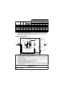
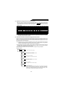
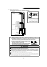
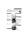
1.3.4 Wiring of the control circuit
(For terminal block functions, refer to “Terminals” on page 58.)
Note: 1.Terminals SD and SE are common to the I/O signals and are isolated from each other. Do not
earth (ground).
2.Use shielded or twisted cables for connection to the control circuit terminals and run them
away from the main and power circuits (including the 200V relay sequence circuit).
3.Since the control circuit input signals are micro currents, use two parallel micro signal contacts
or a twin contact to prevent a contact fault.
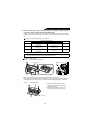
4.Keep the free terminals (NC) unconnected. Otherwise, the high
power factor converter may become faulty.
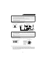
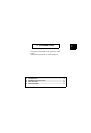
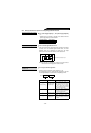
5.When connecting two crimping terminals to one of the control
circuit terminals, round or square open-ended crimping terminals
of the size as shown on the rightshould be used back to back.
CAUTION
Do not use the free terminals (NC) of the control circuit. Using them will lead to the
failure of the high power factor converter and inverter.
Steep distortion or sinking in power may cause the reactor 2 (FR-HCL02) to generate
unusual noise. This phenomenon occurs due to a power fault and is not attributable to
a damaged high power factor converter (FR-HC).
When the load is light, harmonic suppression effects will decrease.
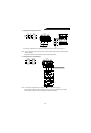
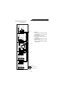
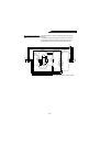
Be sure to connect terminal RDY of the FR-HC to the X10 or MRS signal assigned
terminal of the inverter, and connect terminal SE of the FR-HC to terminal SD of the
inverter. Without proper connecting, FR-HC will be damaged.
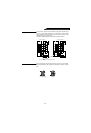
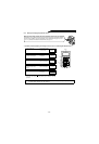
Alarm output
(1 change-over contact output)
Output signals
Converter reset
Converter operating
Meter connection
Open collector
outputs
Contact input common
Overload alarm
Monitor switching
Monitor switching
Converter stop
Reset
External transistor common
A
B
C
(NC)
(NC)
(NC)
(NC)
(NC)
(NC)
(NC)
SE
Y2
Y1
OL
RSO
CVO
RDY
SD
FM
SD
X2
X1
SOF
RES
PC
(NC)
(NC
)
(NC
)
(NC
)
(NC
)
(NC
)
(NC
)
Control input signals (voltage input disabled)
Multi-purpose
output terminal
Multi-purpose
output terminal
Open collector
output common
Inverter operation
enable
Meter connection
common
High
power
factor
converter
(Note)
RA
RDY
CVO
RSO
OL
V1
Y2
SE
Powe
r
suppl
y
24V o
r
12VD
C
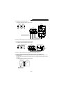
Note: A voltage applied in the wrong
direction will damage the high
power factor converter. Beware
of miswiring such as the
direction of diode connection.
B
B
FF
Note: Round crimping terminal V1.25-MS
3
(Japan Solderless Terminal)
Nominal
B(mm)
1.25-3
6.4 or less
F(mm)
53 or more