


- 20 -
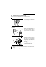
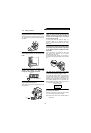
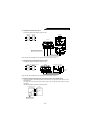
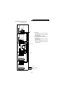
3) Wiring the external box and reactor 2
(Overall wiring distance should be not more than 10m.)
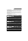
Note: The cable size is dependent on the capacity of the reactor. (Refer to page 17.)
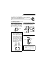
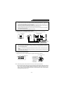
4) Wiring the reactor 2 and high power factor converter
(Overall wiring distance should be not more than 10m.)
Note: The cable size is dependent on the capacity of the reactor. (Refer to page 17.)
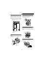
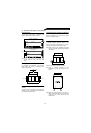
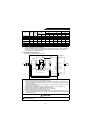
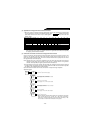
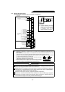
5) Example of how to wire the high power factor converter and inverter (FR-A500 series)
These units should be connected to transmit commands from the high power factor converter to the
inverter securely.
The cable size varies with the inverter series. Refer to the inverter instruction manual for wiring
instructions.
(Overall wiring distance should be not more than 50m.)
Resistor
Magnetic
contactor
S3R3 T3
Terminal block
MC1.MC2
FR-HC
R2 T2
S2
Reactor 2
Overall wiring distance: Within 10m
Power supply
FR-HCL01
Resistor
Transtormer
Capacitor
External box Reactor 2
R2
S2
T2
R3
S3
T3
R3
S3
T3
R4
S4
T4
Reactor 2
High power factor converter
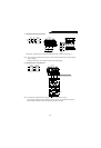
Screw size
Charge lamp
(yellow)
High power
factor converter
M4
R1 S1
RSTR4S4T4
PN
R3 R4 S3 S4 T3 T4
Reactor 2
R4
S4
T4
R3
S3
T3
R4
S4
T4
P
N
High power factor converte
r
High power factor converter
Inverter
P
N
P
N
X10
RES
SD
X11
RDY
RSO
SE
Y1 or Y2
(Note 3)
Control
circuit
Cable size: 0.75 to 2 mm
2