


- 16 -
1.3.2 Wiring instructions
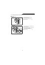
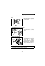
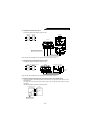
During wiring, do not leave wire off-cuts in the
high power factor converter and external box.
Wire offcuts will cause a malfunction, failure or fault.
The high power factor converter should always be
kept clean.
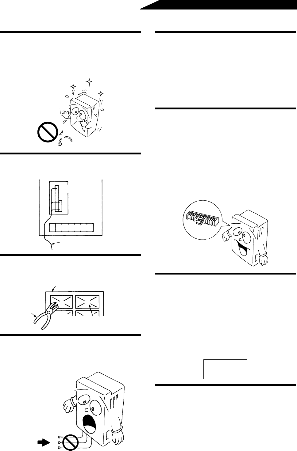
Use the space on the left-hand side of the main
circuit terminal block to run the control circuit
cable.
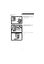
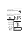
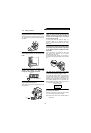
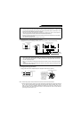
Cut off the wiring cover (protective bush)
windows using nippers or a cutter when
running the cables. (FR-HC-7.5K/H7.5K)
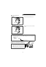
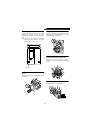
Do not apply a voltage directly to the alarm
output signal terminals (A, B, C).
Always apply a voltage via a relay coil, lamp, etc. to
these terminals.
Before starting wiring or inspection, switch
power off, make sure that the converter LED
indicator has gone off, wait for at least 10
minutes after the charge lamp on the printed
circuit board has gone off.
For some short time after power-off, there is a
dangerous voltage in the capacitor. Start work
about 10 minutes after ensuring that the charge
lamp is off.
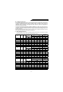
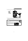
When the power supply voltage is special for the
high power factor converter (the rated input voltage
is exceeded), change the connection of the jumper
in the internal transformer. (FR-HC-H7.5K H15K,
H30K, H55K)
If the connection is not changed, the 400V class
high power factor converter may be heated,
resulting in fault or burnout.
For the FR-HC-H7.5K, change the connection of
the jumper in the internal transformer in the external
box.
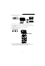
The cable size for connection to the control
circuit terminals should be 0.75mm
2
or less.
If the cable size used is 1.25mm
2
or more, the front
cover may expand, resulting in a contact fault of the
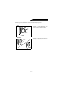
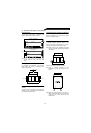
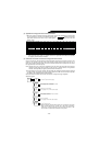
parameter unit. This fault is indicated by the
following message displayed on the parameter unit
and disables operation from the parameter unit.
Run the cables so that they do not occupy much of
the control box terminal block space.
Parameter unit display
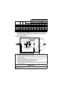
Use shielded or twisted cables for connection to
the control circuit terminals.
Run them away from the main and power circuits
(such as the 200V relay sequence circuit).
Note:Connect the sheath of the shielded cable to
terminal SD.
Wire offcuts, etc.
Control circuit terminal block
Main circuit terminal block
Cable
Wiring cover
Nippers
Cut off.
Protective bush
Voltage
A
B
C
PU to Inverter
comms. Error
Inv. Reset ON
380 to 460V