


- 25 -
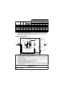
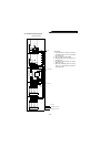
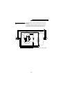
(6) Installation and wiring example
Motor
Power supply
Inverter
R1
S1
U V W
N P
Converter
(FR-HC)
MC1
MC2
R S T
N P
HCB
MC
MC1
NFB
HCL01
HCL02
Main circuit
High-voltage control circuit
Low-voltage control circuit
MC2
(Note 4)
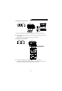
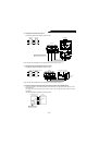
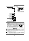
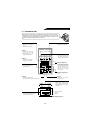
<Vertical mounting>
<Instructions>
1) Leave clearances of at least 10cm above
and below and 5cm on the left and right
side of each unit.
2) Up to six cables may be bundled.
3) Install partitions to shut off heat given to
the upper units.
4) The reactors generate heat. Run cables
away from them.
5) When the installation place has enough
space, it is recommended to install the
units side by side.