


- 70 -
Name (Type) Specifications, Structure, Etc.
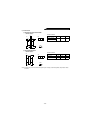
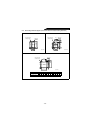
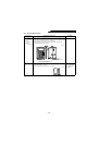
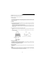
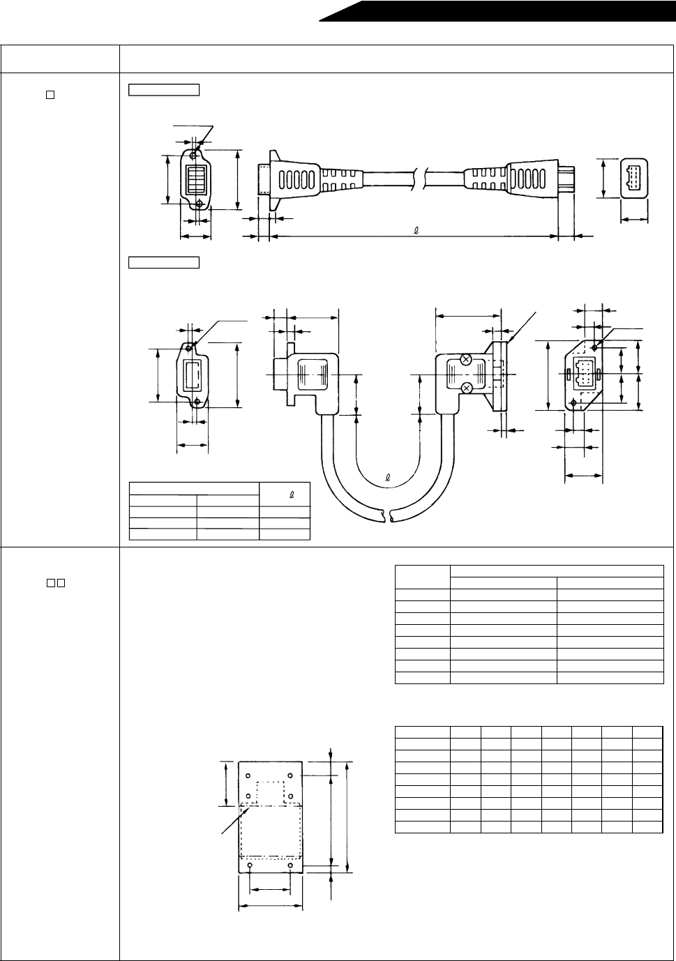
Parameter unit cable
FR-CBL
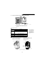
Heat sink outside
mounting attachment
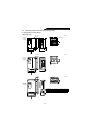
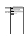
FR-ACN
• By using this attachment, the heat sink acting as
the heat generator of the high power factor
converter can be placed at the back of the control
box. Since the converter-generated heat can be
dissipated to the outside of the control box, the
control box can be made compact.
• For the mounting state and panel cut dimensions,
see the outline drawing (page 66).
Note: Since the cooling fan exists in the cooling
section placed out of the box, do not use
this attachment in environments subjected
to water drops, oil mist, dust, etc.
25
6
+1
-0
3
2-
φ
3.5
2
2
16
32.5
3.5
(2.3)
8.5
5
6
9.5
18
35
13
16.5
15
18.5
20
20
32
26
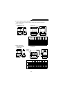
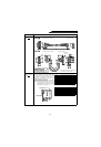
CBL-L1
L
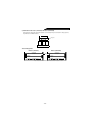
FR-CBL01
FR-CBL03
FR-CBL05
FR-CBL-L1
FR-CBL-L3
FR-CBL-L5
1
3
5
High power factor converter side
L shape type
Parameter unit side
The PU side connector of this L type cable ca
n
be fixed with the accessory screws.
(Removable)
Spacer
2-
φ
3.5
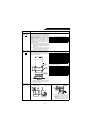
Type
Straight
Length (m)
2
2
15
6
-0
3
9
15
26
32
20
CBL 01
(Unit: mm)
High power factor converter side
Straight type
Parameter unit side
2-
φ
3.5
+1
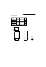
Ty pe
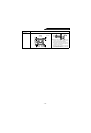
Applicable High Power Factor Converter
200V class 400V class
FR-ACN01
––
FR-ACN02
––
FR-ACN03 FR-HC-7.5K FR-HC-H7.5K
FR-ACN04 FR-HC-15K FR-HC-H15K
FR-ACN05
––
FR-ACN06 FR-HC-30K FR-HC-H30K
FR-ACN07
––
FR-ACN08 FR-HC-55K FR-HC-H55K
(Unit: mm)
Type W W1 H H1 H2 H3 H4
FR-ACN01 150 125 336 320 8 8 17
FR-ACN02 150 125 336 320 8 8 17
FR-ACN03 220 195 336 320 8 8 17
FR-ACN04 280 230 554 530 12 12 122
FR-ACN05 330 280 604 580 12 12 122
FR-ACN06 340 290 682 625 19 38 122
FR-ACN07 460 410 625 590 15 20 80
FR-ACN08 490 430 775 730 17 28 80
W1
W
H4
H2
H1
H
H3
Dimensions after mounting
of the attachment
High power factor
converter outline