


- 22 -
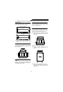
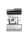
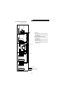
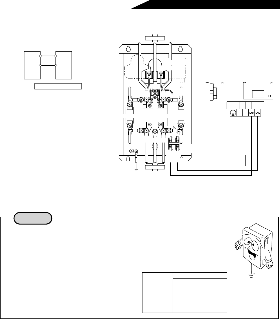
8) Wiring the external box and high power factor converter
Note:Terminals MC1, MC2 of the high power factor converter provide control signals for the inrush current
control circuit within the external box. Always connect these terminals with the external box. Otherwise,
the external box’s internal circuit will be damaged.
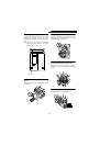
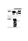
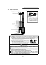
• The high power factor converter leaks current. To prevent an electric shock, always
ground the converter before starting operation (200V class: class D grounding,
grounding resistance 100 maximum, 400V class: class C grounding, grounding
resistance 10 maximum).
• To ground the high power factor converter, use the exclusive ground terminal. (Do
not use the screws in the casing, chassis, etc.)
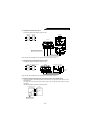
• Use the thickest and shortest possible ground
cable that is equal to, or larger than the size
indicated in the right table. Ground the high
power factor converter at a point nearest to itself
and the inverter.
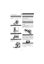
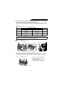
Transformer
Capacitor
Resistor Magnetic contactor
S3R3 T3
Terminal
block
MC1.MC2
FR-HCL02
R2 T2
S2
High power factor converter
Screw size
Control circuit
terminal block
M4
R1 S1
RSTR4S4T4
PN
Overall wiring distance:
Within 10m
FR-HCL01
Power supply
Resistor
External box
MC1
MC2
MC1
MC2
Cable size: 0.75 to 2mm
2
High power factor
converter
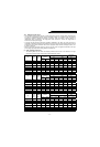
Grounding
(Unit:mm
2
)
High power factor
converter capacity
Ground cable size
200V class 400V class
7.5kW 5.5 3.5
15kW 14 8
30kW 22 14
55kW 38 22
Notes for grounding
Ω
Ω