


- 57 -
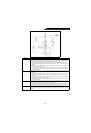
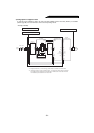
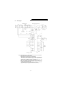
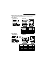
5.1.2 Block diagram
Note: 1.Keep terminals R1, S1 of the high power factor converter unconnected.
2.Except the FR-E500 and A024 series.
3.The parameter unit need not be used for calibration.
This resistor is used for calibration of a remotely located frequency
meter. Note that the needle of the frequency meter may not deflect to
fullscale when the calibration resistor is connected. In this case, use
both the resistor and parameter unit to make calibration.
4.The R, S, T terminals of the high power factor converter (FR-HC) must
be connected to the power supply.
Running the inverter without connecting the terminals to the power
supply will damage the high power factor converter (FR-HC).
FR-HCB(Exlternal box) FR-HC (High power factor converter)
R1S1
R
S
T
R2
S2
T2
R2
S2
T2
FR-HCL01
R
MC
MC
R
R3
S3
T3
R3
S3
T3
FR-HCL02
R4
S4
T4
R4
S4
T4
CHARGE
M
N
P
R1 S1 (Note 2)
R1 S1
MC1
MC2
MC1
MC2
R
S
T
POWER
R1
S1
RES
SOF
X1
X2
SD
CON
FR-PU02E
-1
ALARM
CPU
A
B
C
RA
FM
SD
RDY
CVO
Y1
Y2
RSO
OL
SE
Power supply
Current
detection
Overcurrent
detection
Inverter
Motor
FR series
Meter
Calibration
resistor (Note 3)
Open
collector
output
Ground
(Note 1)
Control
power supply
Phase detection
Filter C