


- 58 -
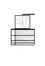
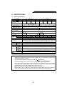
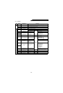
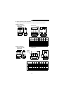
5.1.3 Terminals
Type
Terminal
Symbol
Terminal Name Description
Main
circuit
R, S, T Power input
Terminals for power supply phase, power voltage detection and control power input. Connect
to commercial power supply. Running the inverter without connecting these terminals will
damage the high power factor converter (FR-HC).
R4, S4, T4 Power input Connect to reactor 2.
P, N Inverter connection Connect to P and N terminals of inverter.
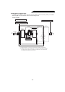
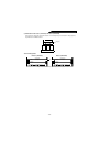
Control ciruit
Input signals
MC1,CMC2 MC connection Connect to MC1, MC2 in external box.
RES Reset
Function Circuit Remarks
Converter operation stop
(used to return from error)
24VDC
sink circuit
Operations of converter and all inverters
connected are stopped.
SDF Converter stop Converter gate shut-off
RDY signal is open.
Inrush MC is closed.
X1
Monitoring switch-over
Selection of FM output and
PU monitor display
• Input current monitor
• Bus voltage monitor
• Input voltage monitor
• Input power monitor
X2
SD Common terminal
Common terminal
(input, FM)
–
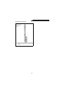
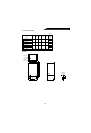
Output signals
RDY Inverter run enable signal
Closed only when alarm
occurs or reset (RES) signal
is input.
Open
collector
Inverter is stopped.
RDY signal open:
Inverter operative
RDY signal closed:
Inverter inoperative
CVO Converter operating Output during IGBT switching
OL Overload alarm
Overcurrent
(150% load or more)
Overvoltage
(output at overvoltage
trip-less operation)
Y1
Multi-Purpose output
terminal
Multi-purpose output
External fault
• Power supply
phase detection signal
• Output voltage match
signal detection
• Instantaneous power
failure detection
• Driving/regenerative
mode judgment
Y2
RSO Converter reset
Output when converter is
reset.
Inverter is reset.
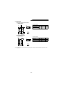
FM Meter connection terminal
Pulse train signal is output in
proportion to input current.
PWM pulse
output
Depends on setting of X1, X2 terminals.
SE
Open collector output
common
Open collector common
–
SD Contact input common Common terminal (I/O, FM)
–
A, B, C Alarm conntact Alarm output
Change-over
contact