


- 71 -
Name (Type) Specifications, Structure, Etc.
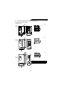
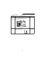
Dirt-protection
structure attachment
FR-ACV
• By installing this option in the slits at the top,
bottom, right and left of the high power factor
converter, the high power factor converter can be
changed to be an enclosed structure model (IP40).
(The box-shaped attachment is added to the wiring
section of 11K to 22K.)
• Adequate for wall mounting application, etc.IP40
(JEM1030): Structure which prevents a wire,
copper band or the like in excess of 1mm in
diameter or thickness from entering into the high
power factor converter.
Note 1: This structure is not protected from water and
fluid entry and is therefore not appropriate for
environments often exposed to water drops
or oily smoke.
Note 2: When this attachment is used, the
permissible ambient temperature of the high
power factor converter is -10°C to +40°C.
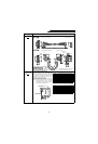
Conduit connection
attachment
FR-AFN
• Used to connect a conduit pipe directly to the
bottom of the high power factor converter.
• By installing this attachment, 11K to 55K (200V,
400V) are changed in structure specification to
IP20. (IP00 is standard.) .
Note: Secured by a total of four places, the two
installation screws at the bottom of the high
power factor converter and the two places at
the bottom of the FR-AFN.
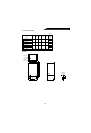
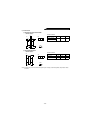
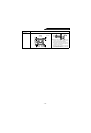
Radio noise filter
FR-BIF 200V class
FR-BIF-H
400V class
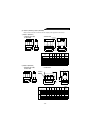
Ty pe
Applicable High Power Factor Converter
200V class 400V class
FR-ACV01
––
FR-ACV02
––
FR-ACV03 FR-HC-7.5K FR-HC-H7.5K
FR-ACV04 FR-HC-15K FR-HC-H15K
FR-ACV05
––
Ty pe
Applicable High Power Factor Converter
200V class 400V class
FR-AFN01
––
FR-AFN02
––
FR-AFN03
––
FR-AFN04
––
FR-AFN05 FR-HC-7.5K FR-HC-H7.5K
FR-AFN06 FR-HC-15K FR-HC-H15K
FR-AFN07
––
FR-AFN08 FR-HC-30K FR-HC-H30K
FR-AFN09
––
FR-AFN10 FR-HC-55K FR-HC-H55K
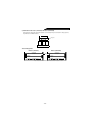
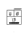
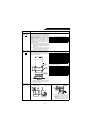
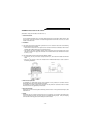
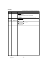
Attachment Outline Drawing (Unit: mm)
Ty pe L H P N D M R
FR-AFN01 45 56 48 2 35 60 6
FR-AFN02 45 71 48 2 35 60 6
FR-AFN03 45 75 48 3 35 60 6
FR-AFN04 45 115 48 3 35 60 6
FR-AFN05 55 115 60 3 44 70 6
FR-AFN06 70 115 68 3 50 90 10
FR-AFN07 145 115 68 4 50 185 10
FR-AFN08 145 95 68 4 50 102.5 10
FR-AFN09 285 120 113 3 91 227.5 12
FR-AFN10 285 120 113 4 91 227.5 12
* Same dimensions as those of the high power factor converter.
FR-AFN
PP
M
L
H
High power factor converter
2-
φ
R hole
N-
φ
D hole
(with rubber bush)
(Installation panel sur
f
ace)
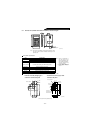
(Note)
*
NFB
R
S
T
Reactor 1
Power
supply
FR-BIF
29 7
44
58
29
42
4
Red Blue Green Leakage current:4mA
(Unit: mm)
Approx. 300
φ
5 hole
White
Note: 1. This filter must not be connected to the
output circuit of the high power factor
converter.
2.The cables should be as short as
possible and connected to the terminal
block of the high power factor converter.