


- 23 -
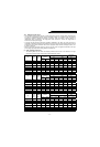
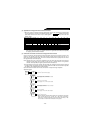
(3) Application of the high power factor converter and inverter
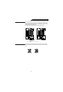
1) When one inverter is connected to the high power factor converter, the capacities of the inverters that
may be connected are as listed in the following selection table. : indicates that the high
power factor converter and inverter may be used together. –: indicates that they cannot be used
together. (Note)
Note: When the inverter connected has a capacity less than in the application range, the high power
factor converter may be used as a common converter or regenerative converter, but its capability
to suppress power harmonics will reduce.
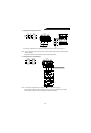
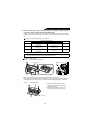
(4) Connection of more than one inverter to the high power factor converter
Up to six inverters may be connected to one high power factor converter. (Do not connect seven or more
inverters.) The capacity of the high power factor converter should always be higher than the sum of
those of the inverters connected. Also, one inverter connected should have a capacity more than half of
the high power factor converter capacity.
Note: Note that if the sum of the inverter capacities is less than half of the high power factor converter
capacity, the high power factor converter may be used as a common converter or regenerative
converter, but its capability to suppress power harmonics will decrease.
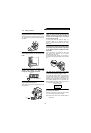
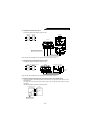
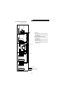
1)For connection of more than one inverter, select the cable size carefully because the inverter terminals
P, N will be wired using junction terminals or jumpers. Select the cable size so that inverter capacities
are added in order, beginning with the farthest inverter.
2)For connection of more than one inverter, connect them in sequence of larger capacities.
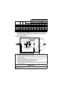
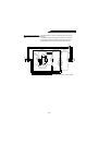
3)Specific example
Motor capacity (kW) 2.2 or less 3.7 5.5 7.5 11 15 18.5 22 30 37 45 55
Inverter capacity (K) 2.2 or less 3.7 5.5 7.5 11 15 18.5 22 30 37 45 55
2
0
0
V
FR-HC-7.5K –
Outside application range
FR-HC-15K –––
Outside application range
FR-HC-30K – ––––
Outside application range
FR-HC-55K – –––––––
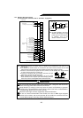
4
0
0
V
FR-HC-H7.5K –
Outside application range
FR-HC-H15K –––
Outside application range
FR-HC-H30K – ––––
Outside application range
FR-HC-H55K – –––––––
FR-HC
55K
A520
30K
A520
15K
A520
5.5K
A520
2.2K
A520
1.5K
A520
0.75K
P
N
P
N
P
N
P
N
P
N
P
N
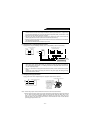
First: 125mm
2
cable from FR-HC capacity
Second: 15+5.5+2.2+1.5+0.75=24.95K
Hence, capacity is 30K, so 50mm
2
cable is selected.
Third: 5.5+2.2+1.5+0.75=9.95K
Hence, capacity is 11K, so 14mm
2
cable is selected.
Fourth: 2.2+1.5+0.75=4.45K
Hence, capacity is 5.5K, so 5.5mm
2
cable is selected.
Sixth: 2mm
2
cable from 0.75K
Fifth: 1.5+0.75=2.25K
Hence, capacity is 2.2K, so 2mm
2
cable is selected.
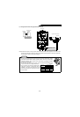
Note: When the FR-E500, FR-A024 series inverters are connected to the high power
factor converter (FR-HC-7.5K), at least one of the inverter connected is
required to be at least half the rating of the high power factor rating. In this
case, at least one of the inverter connected is 3.7K or greater.