


- 32 -
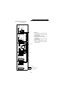
2.2.2 Setting of parameters to improve the corresponding operational functions
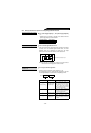
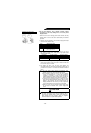
Pr.1 “power supply frequency 1”, Pr.2 “power supply frequency
2”
• Indicates that the converter is operable in the district where the
power supply frequency is 50Hz or 60Hz.
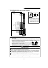
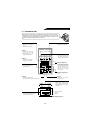
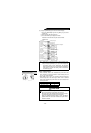
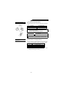
Pr.22 “overload signal detection level”
• If the inrush current of the high power factor converter exceeds the
set value of Pr. 22 “overload signal detection level”, the alarm
detection signal “OL” is displayed and output from the output
terminal “OL”. Set a value with reference to the rated current.
Note: The set value (%) indicates the ratio of the inrush current to
the rated current of the high power factor converter.
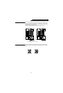
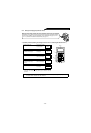
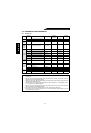
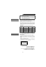
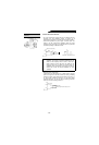
Pr.40 “output terminal assignment”
• Functions can be reassigned to output terminals Y1, Y2.
Set a 2-digit integer in Pr. 40 “output terminal assignment”. The value
of each digit indicates the function of the corresponding terminal.
Parameter Number Factory Setting
1 60.00Hz
2 50.00Hz
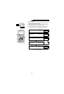
Pr.40 Setting Function Name Operation
0
(Factory setting)
Power supply phase
detection signal
When the input power supply is in
phase with the arithmetic result, the
power supply phase detection signal is
locked. When they are out of phase,
the power supply phase detection
signal is unlocked and output from the
open collector output terminal.
1 Output voltage match
When the bus voltage matches the
command value from the CPU, the
corresponding signal is output from the
open collector output terminal.
2
Instantaneous power
failure detection
This signal indicates that an instanta-
neous power failure occurred.
3
Driving/regenerative
mode judgment
Whether the mode is driving or
regenerative is judged. In the driving
mode, the open collector terminal does
not conduct.
Preset input frequency to the converter
To detect the overload signal
Overload signal detection signal
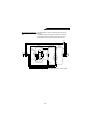
FWD EXT
FR-PU02E
To change the functions of the output
terminals Y1, Y2
Pr.40= First digit Second digit
Y2 Y1