


- 7 -
1.2 STRUCTURE
1.2.1 Structure
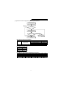
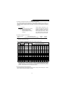
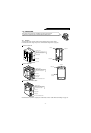
The high power factor converter models have the following parts as shown below.
For the location of the charge lamp, refer to “Terminal block arrangement” on page 60.
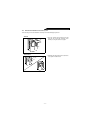
FR-HC-7.5K/H7.5K
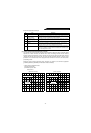
FR-HC-15K/H15K
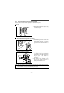
FR-HC-30K, 55K/H30K, H55K
Note:Dimensions vary with the capacity. For full information, refer to “Outline Dimension Drawings” on page 61.
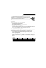
This section covers the structure, installation and removal of the equipment.
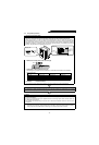
In this manual, equipment parts are described with the following names.
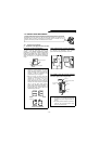
When using the parameter unit, re-
move this accessory cover and install
the parameter unit in this position.
Accessory cover
Front cover
Capacity plate
Rating plate
Chassis
Cooling air
Capacitors
Cooling fan
Capacity plate
Rating plate
Front cover installation screws
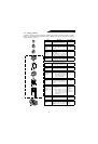
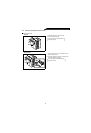
When using the parameter unit, re-
move this accessory cover and install
the parameter unit in this position.
Front cover
Accessory cover
Cooling air
Cooling fan
Chassis
(Plastic)
Capacity plate
Rating plate
Front cover installation screws
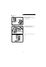
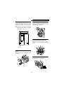
When using the parameter unit, re-
move this accessory cover and install
the parameter unit in this position.
Front cover
Accessory cover