


- 47 -
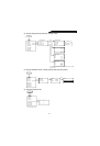
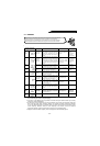
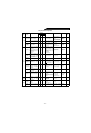
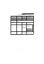
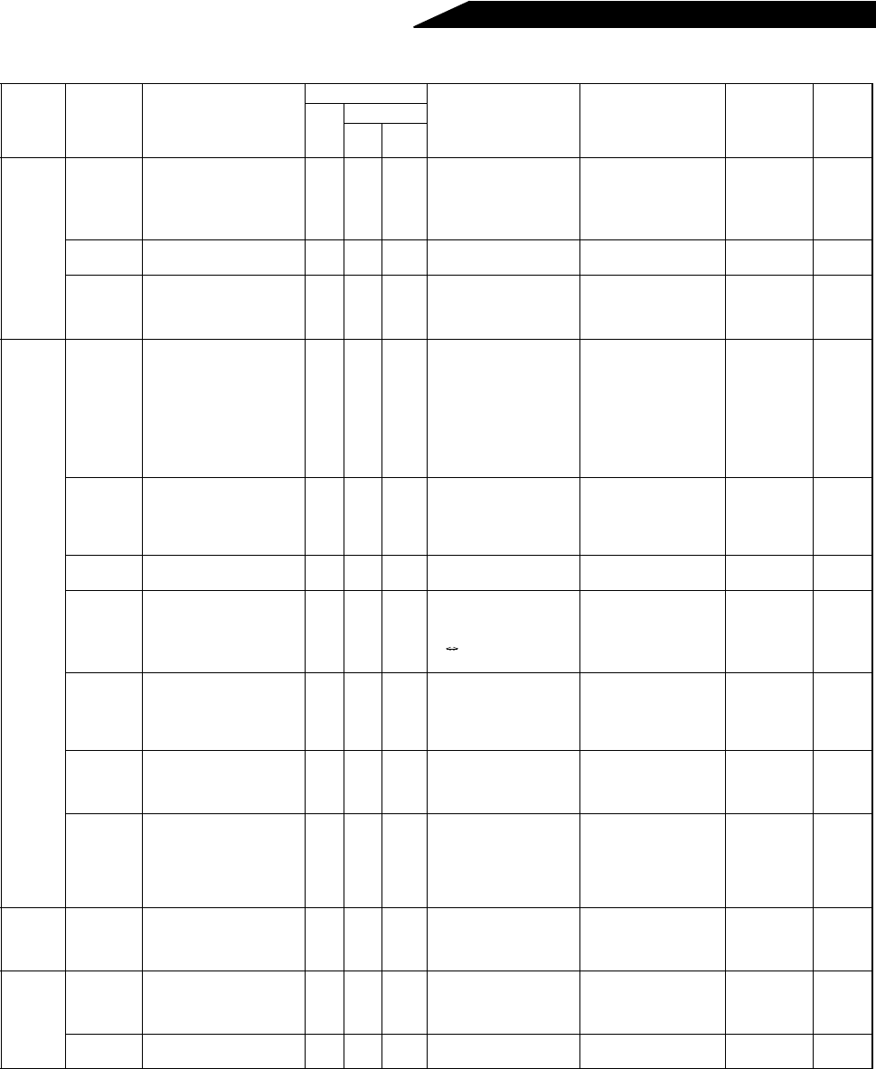
Daily and Periodic Inspection
Note:Values for the 400V class are indicated in parentheses.
Area of
Inspec-
tion
Inspection
Item
Description
Interval
Method Criterion Instrument
Customer
setting
Daily
Periodic
1
year
2
years
General
Surrounding
environment
Check ambient temperature,
humidity, dust, dirt, etc.
!
See note on page 13.
Ambient temperature:
-10°C to +50°C, non-
freezing.
Ambient humidity: 90%
or less, non-condensing.
Thermometer,
hygrometer,
recorder
Overall unit
Check for unusual vibration
and noise.
!
Visual and auditory
checks.
No fault.
Power
supply
voltage
Check that main circuit
voltage is normal.
!
Measure voltage across
high power factor
converter terminals R, S,
T-P4, S4, T4.
170 to 242V
(323 to 506V) 50Hz
170 to 253V
(323 to 506V) 60Hz
Tester, digital
multimeter
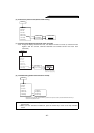
Main
circuit
General
(1) Check with megger
(across main circuit
terminals and ground
terminal).
(2) Check for loose screws
and bolts.
(3) Check for overheat on
each part.
(4) Clean.
!
!
!
! (1) Disconnect all cables
from high power factor
converter and measure
across terminals R4,
S4, T4, P, N and
ground terminal with
megger.
(2) Retighten.
(3) Visual check.
(1) 5M or more.
(2), (3) No fault.
500VDC class
megger
Conductors,
cables
(1) Check conductors for
distortion.
(2) Check cable sheaths
for breakage.
(3) Check for discoloration.
!
! (1), (2) Visual check. (1), (2) No fault.
Te rm in a l
block
Check for damage. ! Visual check No fault
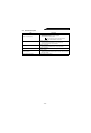
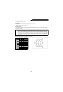
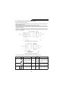
Converter
module
Check resistance across
terminals.
!
Disconnect cables from
converter and measure
across terminals R4, S4,
T4 P, N with tester ×1
range.
(See the next page.) Analog tester
Smoothing
capacitor
(1) Check for liquid leakage.
(2) Check for safety valve
projection and bulge.
(3) Measure electrostatic
capacity.
!
!
!
(1), (2) Visual check.
(3) Measure with capac-
ity meter.
(1), (2)
No fault.
(3)85% or more of
rated capacity.
Capacity
meter
Relay
(1) Check for chatter during
operation.
(2) Check for rough surface
on contacts.
!
!
(1) Auditory check.
(2) Visual check.
(1) No fault.
(2) No fault.
Resistor
(1) Check for crack in
resistor insulation.
(2) Check for open cable.
!
!
(1) Visual check. Cement
resistor, wirewound
resistor.
(2) Disconnect one end
and measure with
tester.
(1) No fault.
(2) Error should be
within ±10%
of indicated
resistance value.
Tester, digital
multimeter
Cooling
system
Cooling fan
(1) Check for unusual
vibration and noise.
(2) Check for loose
connection.
!
!
(1) Turn by hand with
power off.
(2) Retighten.
(1) Smooth rotation.
(2) No fault.
Display
Display
(1) Check for power lamp
blown.
(2) Clean.
!
!
(1) Lamps indicate
indicator lamps on
panel.
(2) Clean with rag.
(1) Check that lamps
are lit.
Meter
Check that reading is
normal.
!
Check reading of meters
on panel.
Must satisfy specified
and management
values.
Voltmeter,
ammeter, etc.
Ω
Ω