


B-2 Memory Configurations
Memory DIMM Configurations
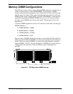
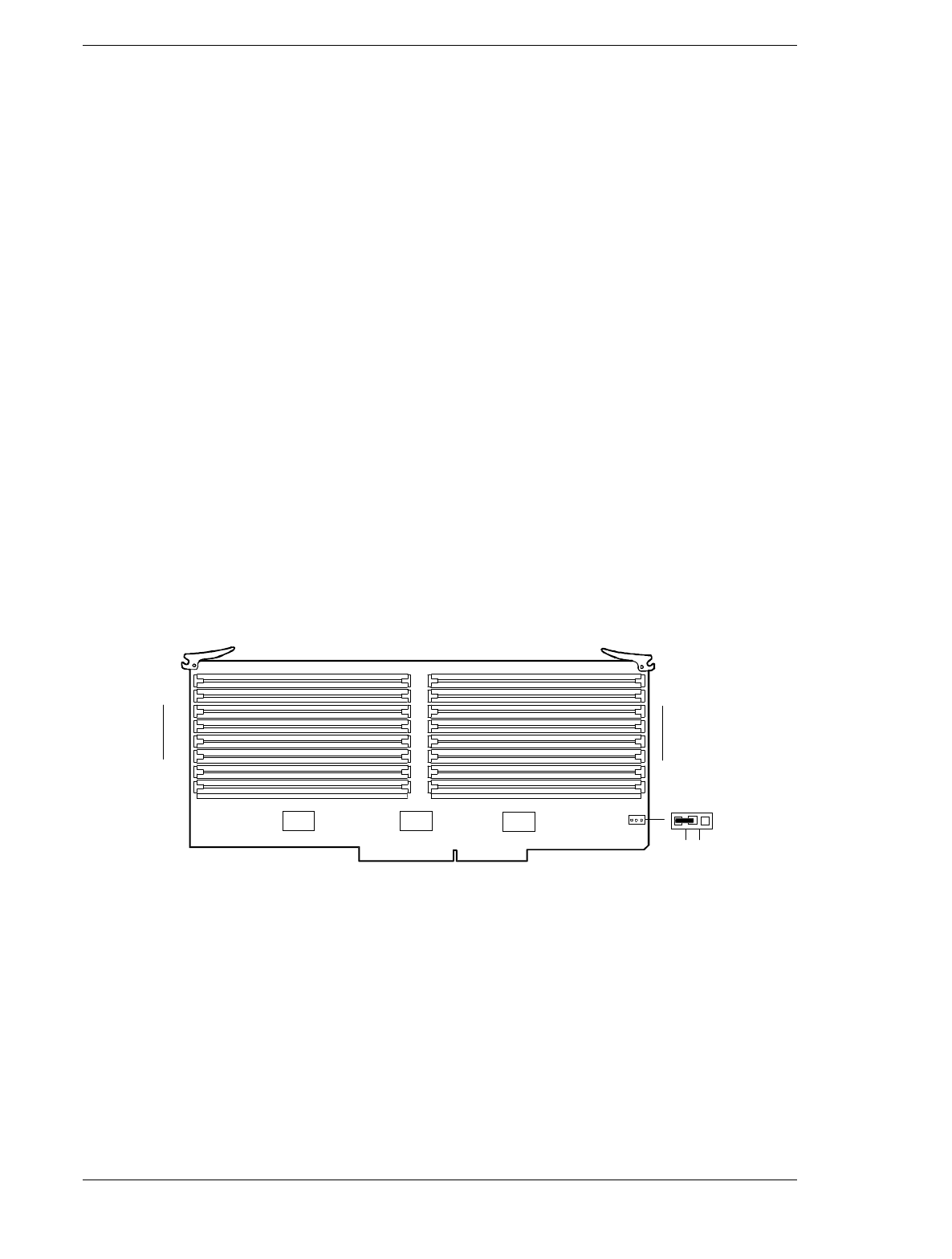
The CPU base board contains sixteen 168-pin DIMM sockets for a total of up to
4 GB of system memory, using 256MB DIMMs. See Figure B-1. DIMM
sockets on the board are organized as four 144-bit wide (122-bit wide data path
with 16 parity bits) banks. Parity generation/checking is provided for each byte.
DIMM sockets accept 168-pin single- or double-sided DIMMs. A bank must be
populated using identical DIMMs. DIMMs may vary in size from one bank to
the other, but all DIMMs must be the same speed. Timing requires 60 ns fast
page devices.
A memory DIMM upgrade kit consists of 4 identical (of the same size and type)
DIMMs defined as:
4 x 32MB DIMMS = 128MB
4 x 64MB DIMMs = 256MB
4 x 128MB DIMMs = 512MB
4 x 256MB DIMMs = 1GB.
The first bank of DIMMs should be installed in sockets P02, P03, P04 and P05.
When you install additional DIMMs, you must start with bank 2 and continue to
bank 4. When you remove DIMMs, you must start with the highest populated
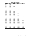
bank of DIMMs. Table B-1 lists the distribution of DIMMs for system memory
configurations that maximize socket availability, other combinations are
possible.
A
B
C
D
P03
P05
P15
P17
P02
P04
P14
P16
60 50
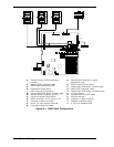
Figure B-1. CPU Base Board DIMM Sockets