


Upgrading Your System 4-15
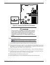
DIMMs
The memory board contains sixteen DIMM sockets arranged in four banks (see Figure
1-8). Each 168-pin socket can hold a single 72-bit DIMM module with 32MB, 64MB,
128MB, or 256MB of memory. When all sixteen sockets are populated, the memory
board supports a maximum of 4GB of memory with 256MB DIMMs. DIMMs must be
identical within a bank.
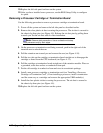
The first bank of DIMMs should be installed in sockets P02, P03, P04 and P05 (see
Figure 4-7). When you install additional DIMMs, you must start with bank 2 and
continue to bank 4. When you remove DIMMs, you must start with the highest
populated bank of DIMMs.
The following provides procedures for configuring the memory in your system.
!
WARNING
If the system was running, any processor and heat sink installed is
hot. To avoid the possibility of a burn while configuring memory, let
the components cool for 10 minutes before continuing with the
procedures described here.
A
B
C
P17
P15
P13
P11
P09
P07
P05
P03
P16
P14
P12
P10
P08
P06
P04
P02
Bank
D
C
B
A
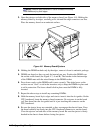
Figure 4-7. Inserting Memory DIMMs
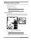
Installing DIMMs
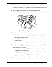
When properly installed, the DIMM module is oriented at an angle of 90 degrees
relative to the memory board.
1.
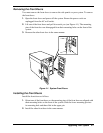
Power off the system and remove the left side panel as described earlier.
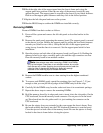
2.
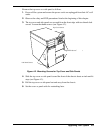
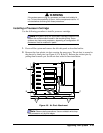
Remove the metal panel supporting the memory board. The support panel is secured
to the chassis by two black fasteners. Release each fastener by slowly pulling it
towards you (listen for two clicks). Grasp the left side of the support panel and
swing it away from the chassis to remove it. Set the support panel aside for later
installation.