


Upgrading Your System 4-25
Controller/Adapter Hardware Configurations
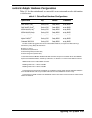
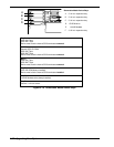
Table 4-1 lists the option boards you may add to your system and provides information
on slot location.
Table 4-1. Option Board Hardware Configurations
Option Board Irq
2
Memory
Address I/O Address
SMC 9432TX (1st)
3
Set by BIOS Set by BIOS Set by BIOS
SMC 9432TX (2nd)
3
Set by BIOS Set by BIOS Set by BIOS
3COM 3c905B (1st)
3
Set by BIOS Set by BIOS Set by BIOS
3COM 3c905B (2nd)
3
Set by BIOS Set by BIOS Set by BIOS
Adaptec 3940UW
1, 4
Set by BIOS Set by BIOS Set by BIOS
Mylex DAC960
1, 4
Set by BIOS Set by BIOS Set by BIOS
Onboard 7895 SCSI Set by BIOS Set by BIOS Set by BIOS
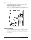
1. For disk controllers plugged into slots and the onboard disk controllers, the sequence for BIOS scanning to
determine the primary (Boot) disk controller is:
ISA slots P11 and P12
PCI slot P2 and P3 (first PCI bus)
Onboard 7895 SCSI (first PCI bus)
PCI slot P4 through P6 (second PCI bus)
PCI slot P7 through P10 (third PCI bus).
It’s recommended that the BIOS be disabled on all SCSI controllers except for the controller with the boot disk drive
attached (see SCSISelect Utilities in Chapter 3, “ Configuring Your System”. This saves memory address resources
and provides control over the boot device independent of board slot locations.
2. Additional IRQs can be made available as follows:
Disabling Comm Port 1 = IRQ4 is available
Disabling Comm Port 2 = IRQ3 is available
Disabling Parallel Port = IRQ7 is available.
3. A maximum of five LAN channels consisting of any combination of single or dual channel. Install ISA LAN card in
the first available ISA slot from the top. Install PCI LAN card in the first available PCI slot from the top.
4. A maximum of four SCSI controllers may be installed. Install the first controller card in PCI slot P2 and the second
controller in PCI slot P3.