


1-10 System Overview
J
H
I
G
D
B
C
A
EF
K
P
LONM
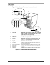
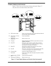
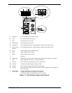
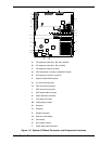
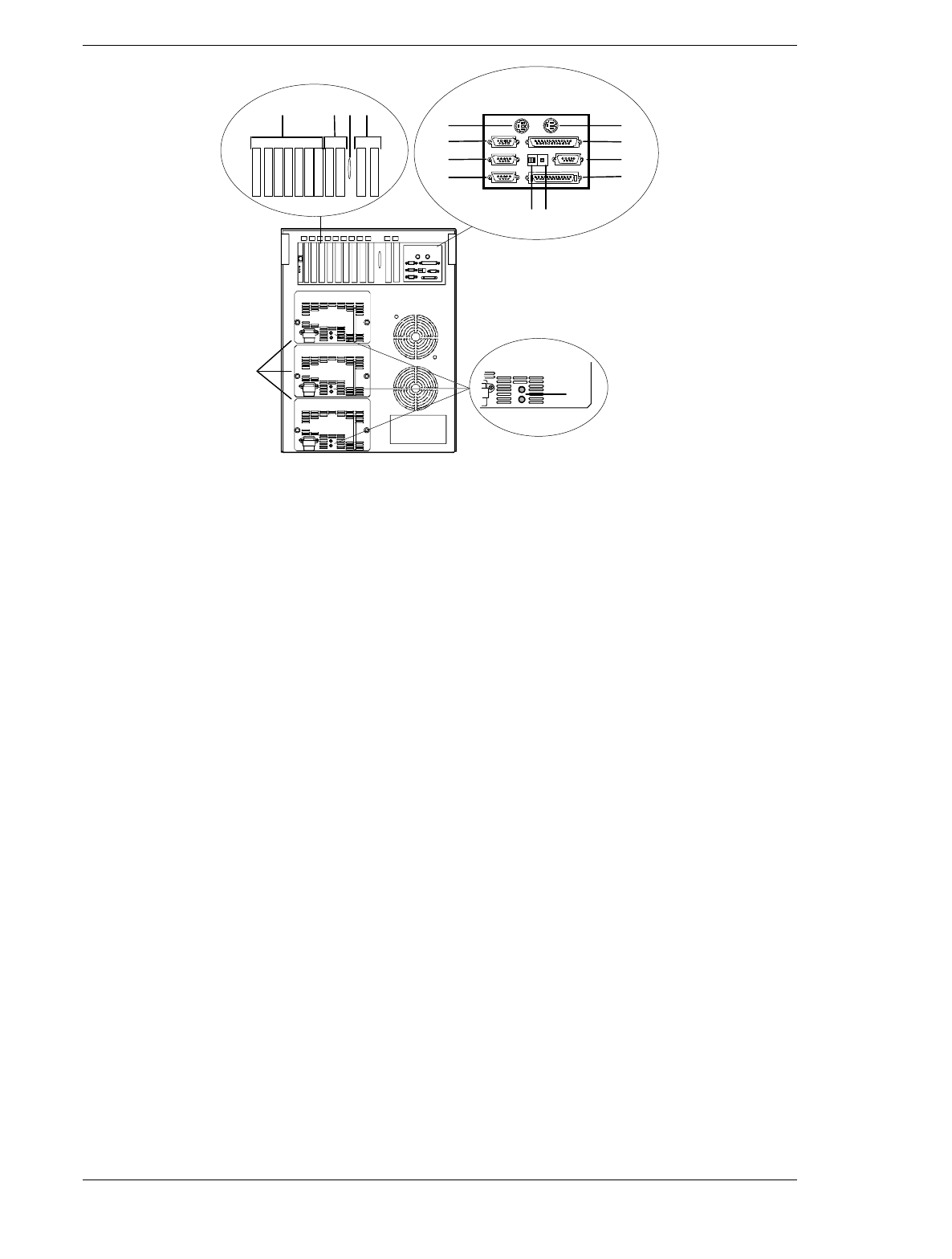
A Keyboard PS/2-compatible 6-pin mini-DIN connector.
B Printer LPT1 25-pin parallel port connector.
C VGA VGA monitor 15-pin connector.
D External-SCSI Narrow-SCSI 50-pin connector
E Dump button
See
Configuring Switch and Jumper Settings
in Chapter 4 of this User’s Guide.
F Function select
switches
See
Configuring Switch and Jumper Settings
in Chapter 4 of this User’s Guide.
G Mouse PS/2-compatible 6-pin mini-DIN connector.
H COM1 COM1 serial port 9-pin connector.
I COM2 COM2 serial port 9-pin connector.
J — Reserved.
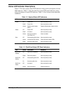
K Power status
LEDs
Both indicators are green during normal operation. Either or both indicators go off when
power supply fails. See Table 1-1 for status descriptions.
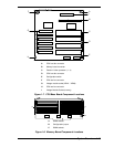
L PCI slots Two PCI add-in board slot locations (PCI #11 and PCI #12).
M Knockout Available to route SCSI signals to peripheral boxes.
N ISA slots Two ISA add-in board slot locations (ISA #1 and ISA #2).
O PCI slots Seven PCI add-in board slot locations (PCI #21, PCI #22, PCI #23, PCI #31, PCI #32, PCI
#33, and PCI #34).
P Power supplies
(three shown)
Possible configurations, installed from bottom most bay:
2 supplies (nonredundant), 3 supplies (one redundant).
Each power supply has a separate AC input power connector.
Figure 1-3. Rear Chassis Features and Controls