


Page 19CPV550
2.4 GPS ANTENNA
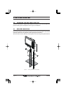
2.4.0 Mounting the GPS WAAS Smart Antenna
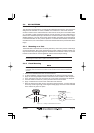
The CPV550 is supplied with a 12 Channel GPS WAAS Smart antenna. This antenna is
designed to be mounted on a base, installed on an extension or even flush mounted.
Choose a location for the antenna that has a clear view of the sky and is not located within
3 FT of Radar or other transmitting antenna. Ensure there are no major obstructions or
fixtures in the immediate proximity to the antenna. The antenna relies on direct “line of sight”
satellite reception. If you are unsure of the chosen location, temporarily mount the antenna
in the desired location to verify correct operation. If mounted close to Radar, and after the
CPV550 has a fix, turn on the Radar to ensure the CPV550 holds the fix (use the GPS Status
Page).
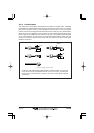
2.4.1 Mounting on a Pole
The thread used on the antenna is an industry standard (1 inch 14TPI) used on a wide range
of mounting brackets. Due to the manufacturing process of these mounting brackets you
may see some slop when tightening down the antenna to the bracket. This is no concern
however as the antenna must be tightened until the antenna stops rotating.
NOTE
The antenna cable can be cut and spliced to ease installation. Care must be taken when
reconnecting the antenna cable to protect from water and corrosion.
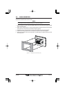
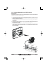
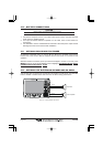
2.4.2 Flush Mounting
NOTE
Before drilling holes, it is recommended the antenna be positioned where the location is planned
to be drilled, cable connected to the CPV550 and the CPV550 turned on to ensure a GPS Fix is
received.
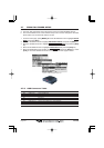
1. Remove the threaded base from the antenna dome.
2. To ease installation a flush mounting template for the antenna has been included.
3. Apply the mounting template sticker to the area that was verified for GPS reception.
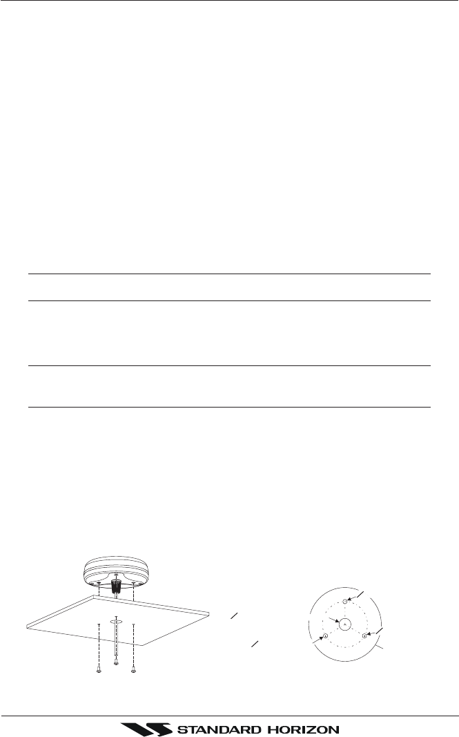
4. Then, drill out the 0.63” (16 mm) and 0.16” (4 mm) holes, and remove the template.
5. Insert the cable into the 0.63” (16 mm) hole and route to the CPV550.
6. Apply a small amount of RTV to the under side of the antenna.
7. Place the antenna and then screw it into place using the screws. In some cases the
screw may not be long enough, if this happens simply apply more RTV to the underside
of the antenna to glue it into place.
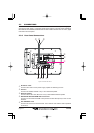
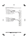
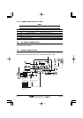
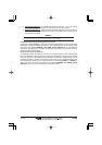
GPS OVERALL SHAPE
CUTTING TEMPLATE
CUTTING TEMPLATE
4 mm [0.155"]
4 mm [0.155"]
0
0
16 mm [0.63"] or greater
0
0
4 mm [0.155"]
Figure 2.3.2 - Installing the GPS WAAS Smart antenna