


Page 21CPV550
2.6.0 Output Sentences
GLL, VTG, BWC, WCV, APA, APB, HDG, BOD, XTE, RMA, RMB, RMC, GGA, HSC, DBT,
DPT, MTW, VWH, MWV
2.6.1 Input Sentences
VHF Radio - DSC, DSC
Radar - TLL
AIS Receiver - VDM
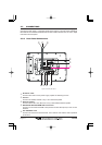
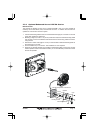
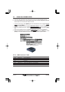
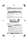
2.6.2 Cables
The CPV550 is supplied with two accessory cables used with AUX 1 and I/O connectors on
the rear panel. Below is the pin out and connection examples of the cables.
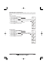
2.6.3 I/O Connector Table
Pin Wire Color Description Connection Example Additional Information
1 Black --- No Connection
2 Red --- No Connection
3 Green NMEA Common Common for NMEA devices
4 Blue NMEA Input Port 1 Conncect to output of NMEA device Default is NMEA0183
5 Brown NMEA Output Port 1 Conncect to intput of NMEA device Default is NMEA0183 with GLL. RMB, RMC, and XTE sentences
6 Gray NMEA Input Port 2 Conncect to output of NMEA device Default is NMEA0183
7 White NMEA Output Port 2 Conncect to intput of NMEA device Default is NMEA0183 with GLL. RMB, RMC, and XTE sentences
8 Yellow NMEA Output Port 3 Connect autopilot Default is NMEA0183 with APA. APB, XTE, COG, and BOD sentences
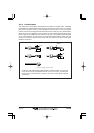
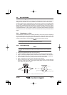
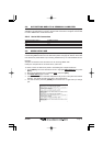
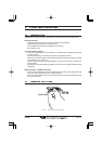
2.6.4 AIS Receiver Setup
Connect the NMEA output and NMEA common wires of the AIS receiver to the Port 1 (blue
and Green wires. For the Chart Plotter to show AIS targets the NMEA in/out Connections
menu must be changed to AIS 38400 as shown below.
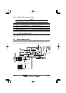
1. From the Chart page, press [MENU]. Move the ShuttlePoint knob to highlight
SETUP
MENU and press the [ENT].
2. Move the ShuttlePoint knob to highlight
ADVANCED SETUP and press the [ENT] key.
3. Move the ShuttlePoint knob to highlight
IN/OUT CONNECTIONS and press the [ENT]
key.
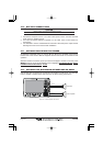
4. Move the ShuttlePoint knob to highlight
PORT1 INPUT and press the [ENT] key.
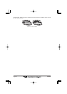
5. Move the ShuttlePoint knob up/down to select
AIS 38400 and press the [ENT] key.
6. Press [CLR] or move the ShuttlePoint knob to the left until the Chart page is shown.