


Page 20 CPV550
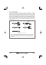
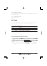
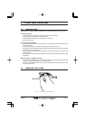
2.4.3 SMART GPS Connector Table
NOTE
This table shown only as a reference for the GPS Smart Antenna. The Smart Antenna is capable
of being directly plugged into the CPV550.
Pin Wire Color Description Connection Example
1 Red Battery Positive Connect to Battery Positive and Red wire of GPS Antenna
2 Green Smart GPS NMEA Input Connect to Smart GPS Input
3 Brown Smart GPS NMEA Output Connect to Smart GPS Output
4 NC --- ---
5 NC --- ---
6 Black/Yellow Battery Ground Connect to battery ground and Black wire of GPS Antenna
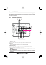
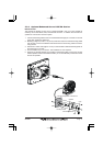
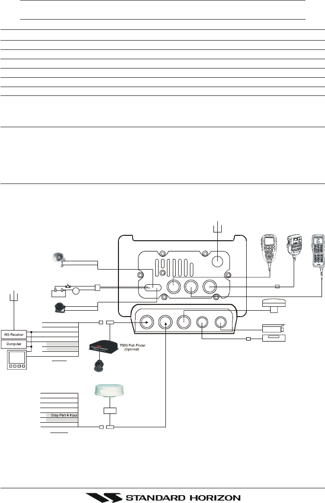
2.5 PA HORN CONNECTIONS
The CPV550 can be connected to the 220SW or 240SW PA horn to hail other vessels or
send FOG, bells or whistles.
2.6 NMEA CONNECTIONS
The CPV550 may be connected to external AIS receivers, Depth Sounders, Speed Logs,
Wind Instruments, temp instruments, VHF radios with NMEA 0183 output.
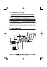
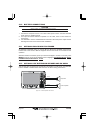
GPS ant
RAM+
VHF Ant
FRONT
PANEL MIC
VH-310
Red
BATTERY
White
Red
Green NMEA Common
Gray Port 2 Input
Green NMEA common
Red No Connection
Red No Connection
Black No Connection
Black NMEA common
White Port 4 Output
Yellow No Connection
Black
Bare Shield
Bare Shield
Blue Port 1 Input
Brown Port 1 Output
White Port 2 Output
Yellow Port 3 Output
Te e
Te e
Transducer
RADAR antenna
(optional)
VIDEO
VIDEO 1GPSAUX
1 RAM 2
I/O
VIDEO 2
DVD
ACVC10 Cable
MEK4Extension Cable
-
Pilot
I/O Cable
Note:
Gray and White wires should
not be connected to other
devices when the FF520 is
connected.
AUX Cable
J Box
6A
Fuse
Blue No Connection
Brown No Connection
Note:
Gray and White wires should
not be connected to other
devices when a RADAR antenna
is connected.